I was the owner of the powder recoating subsystem on a new SLS (Selective Laser Sintering) printer
Rapidly designed and built a modular testbed to de-risk performance concerns and test a few architecture variables
Was able to choose the best path forward, and successfully integrated my design into the fully functional printer prototype on time
2022 - 2023
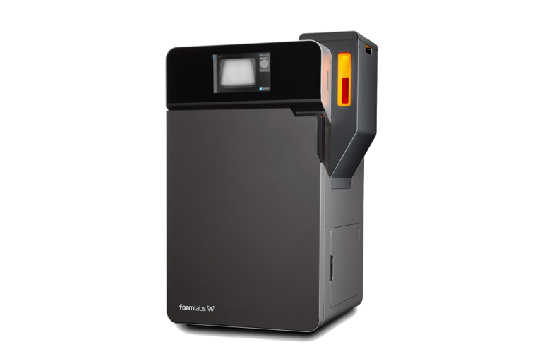
Fuse Blast
Parts printed on Fuse 1 are embedded in a “cake” of powder. Most of the unsintered powder is then reclaimed using Fuse Sift, but simply brushing parts isn’t enough to make them clean to the touch, so Formlabs also recommends media blasting parts with fine glass bead to be fully clean
A pain point for SLS printing with the Fuse 1 was the time and effort to do final part cleaning, especially for larger quantities of parts. Despite being a necessary part of the SLS workflow, Formlabs didn’t previously sell a media blaster, so a good opportunity existed to complete the ecosystem
Established automated media blasters designed for SLS parts often retailed starting at $30k, such as from AM Solutions or DyeMansion, so a good opportunity also existed to provide a lower cost product for all SLS users, not just those using Formlabs products
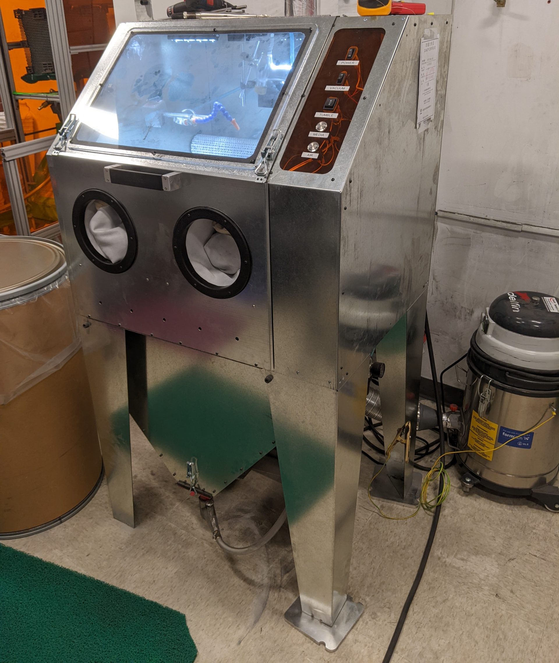
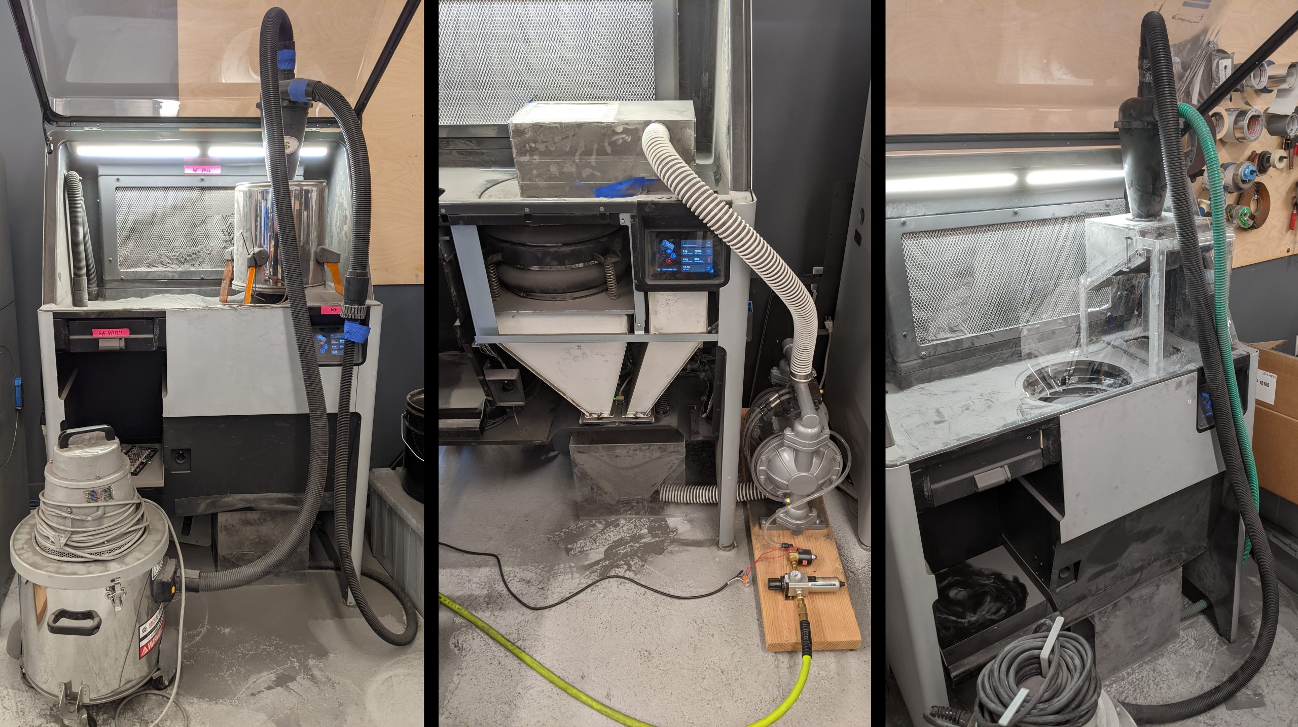
Initial Fuse Blast Experiments Hacked on OTS Sandblast Cabinet
The first prototype for a Formlabs media blaster started with hacking away at a sandblasting cabinet to automate and improve the workflow
A common solution for automation is to tumble parts in a rotating basket underneath the media blast spray
An alternate solution in industry is to use a conveyor belt tumbler
I threw together the belt tumbler shown on the left, and it worked reasonably for a hacky prototype
One of the easier pain points to address with low cost sandblast cabinets is poor lighting, so I swapped the stock tube lights for LEDs that matched the brightness and color temperature of the lights on Sift
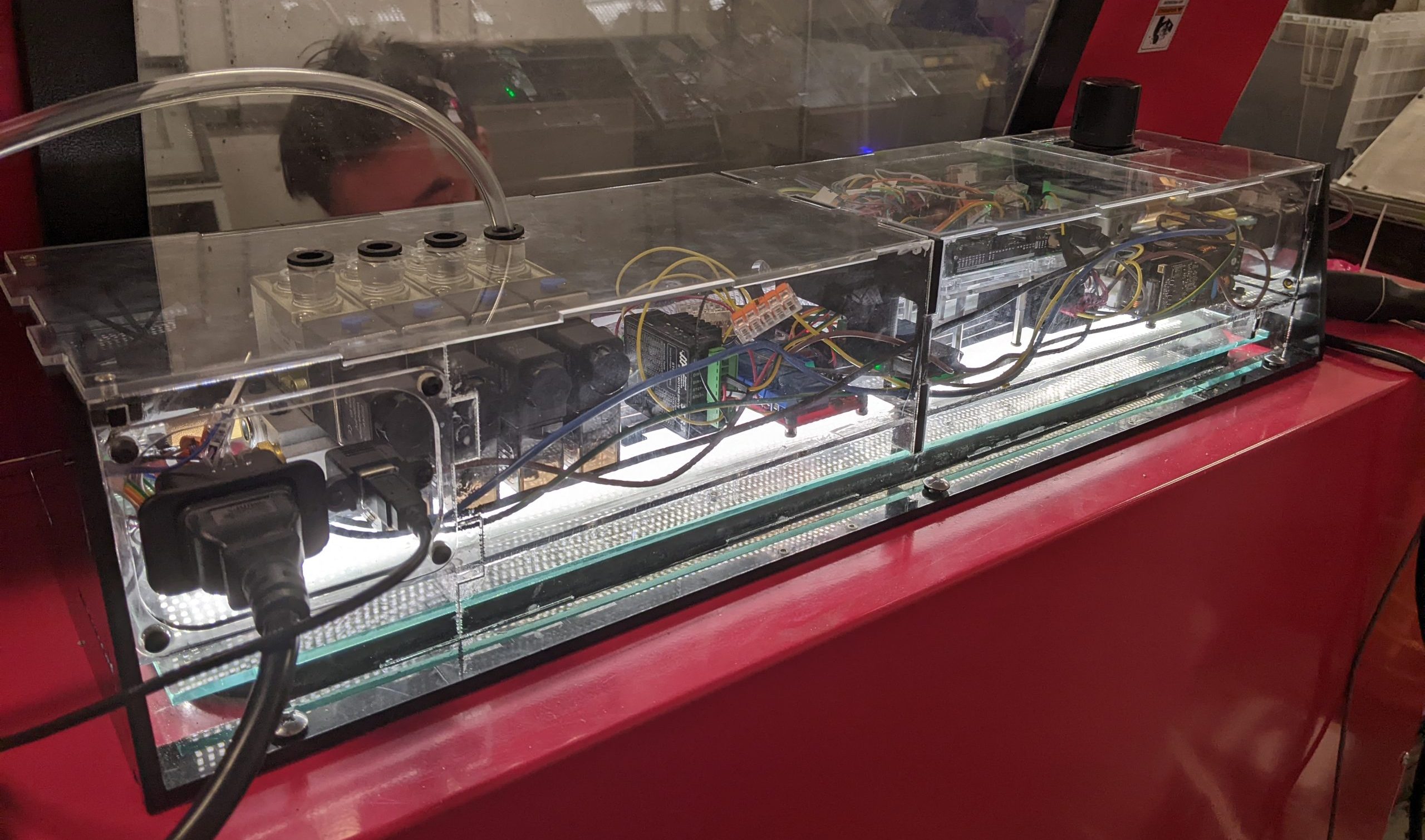
We also wanted to automate the blast cycle, so I made a box with an Arduino to control a stepper driver, 120v relay for dust extraction, and multiple solenoids for automated blasting, air rinsing, cabinet rinsing, and manual blasting
My Lighting and Automation Control Box
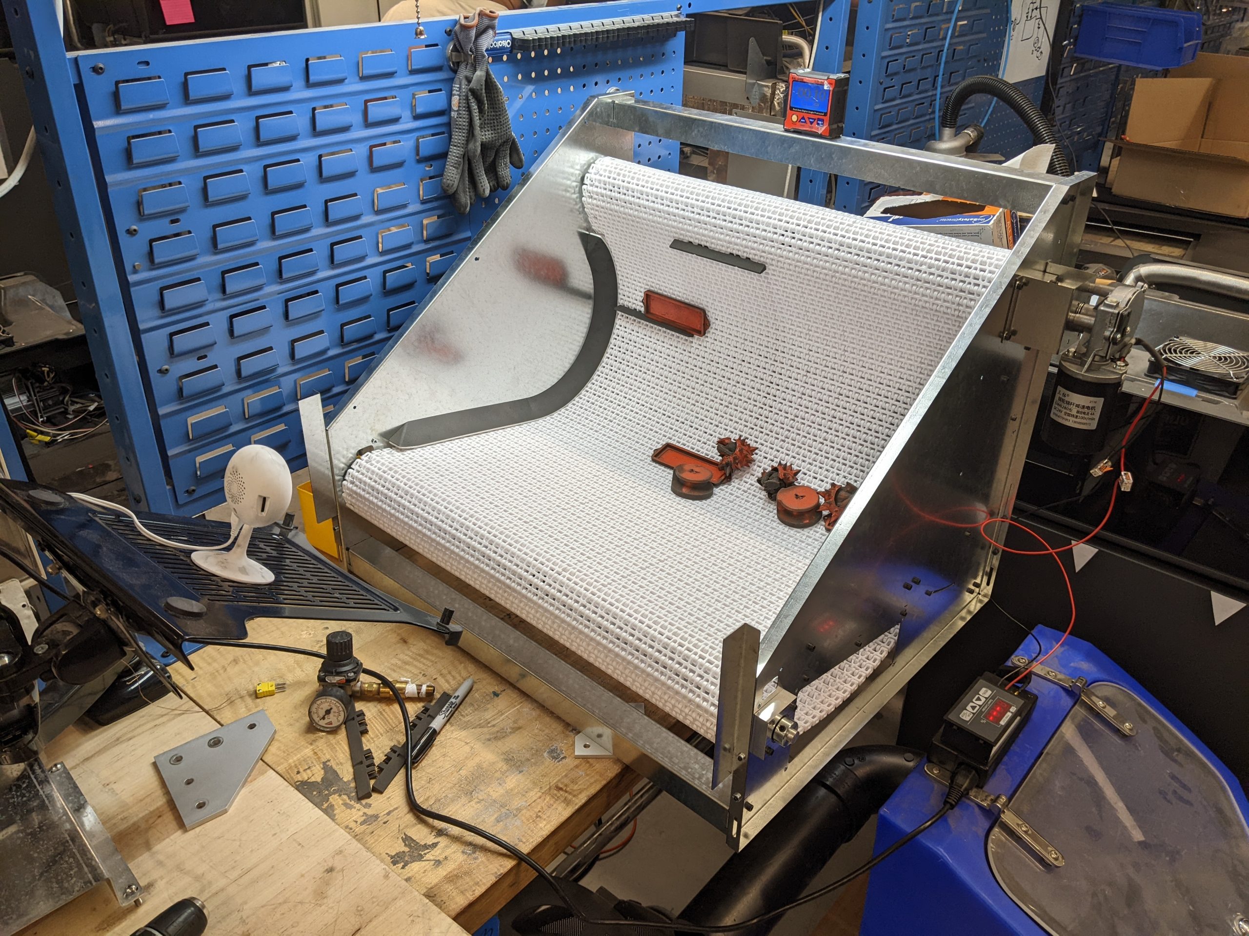
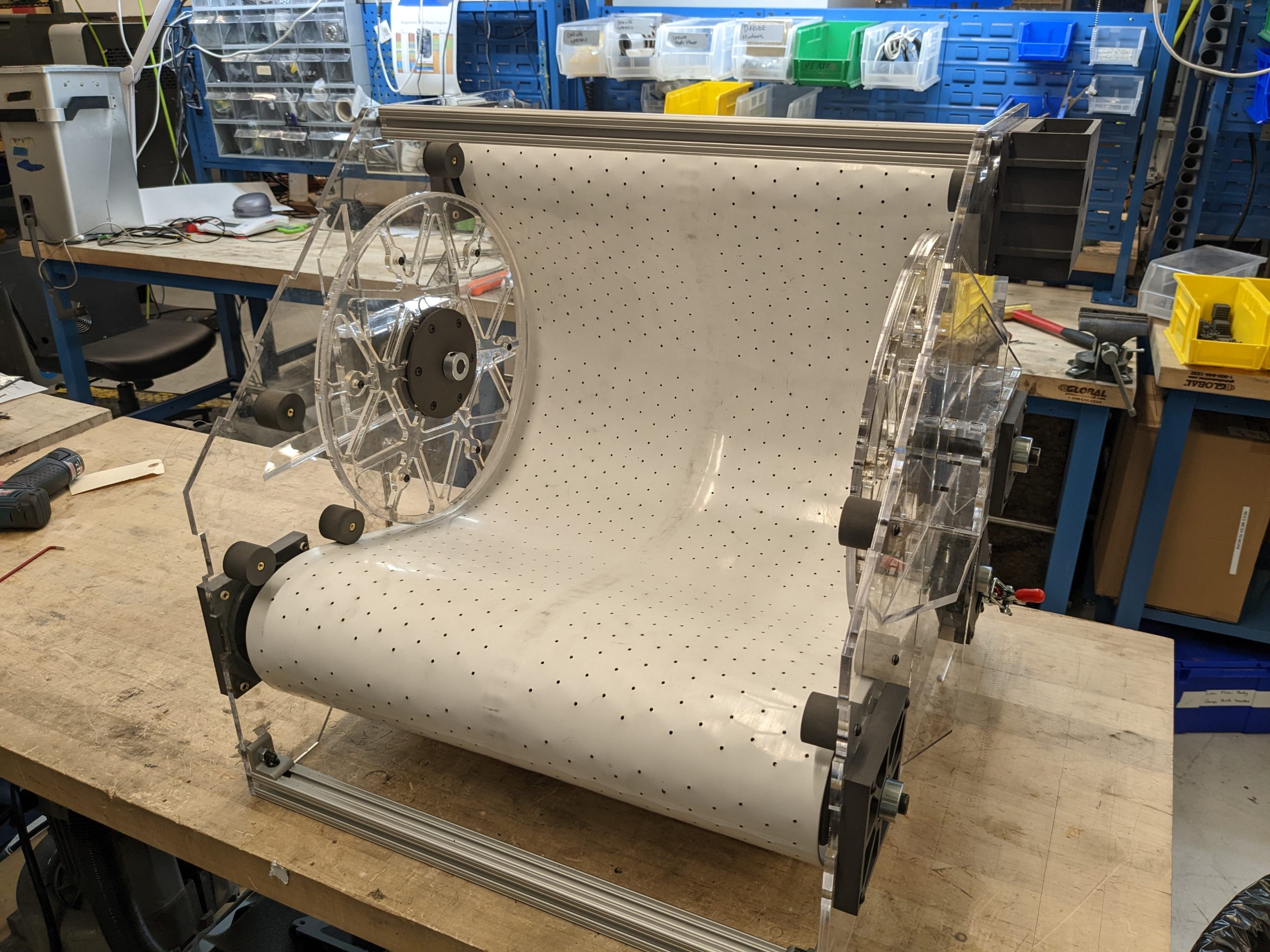
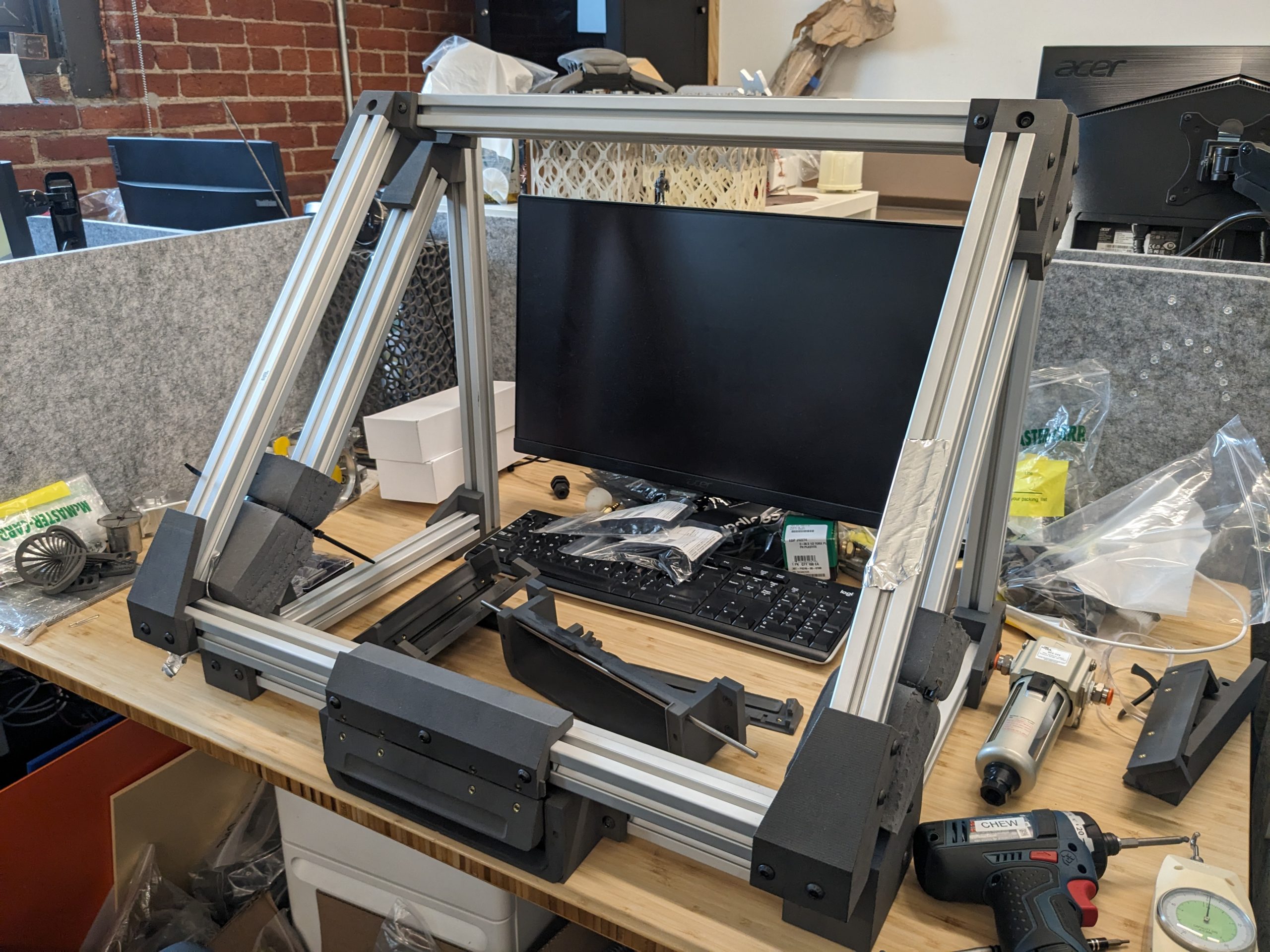
Improved Belt Tumbler Prototype
With improved knowledge on conveyor belt design I created a better second prototype
The setup shown was used to conduct experiments on part agitation
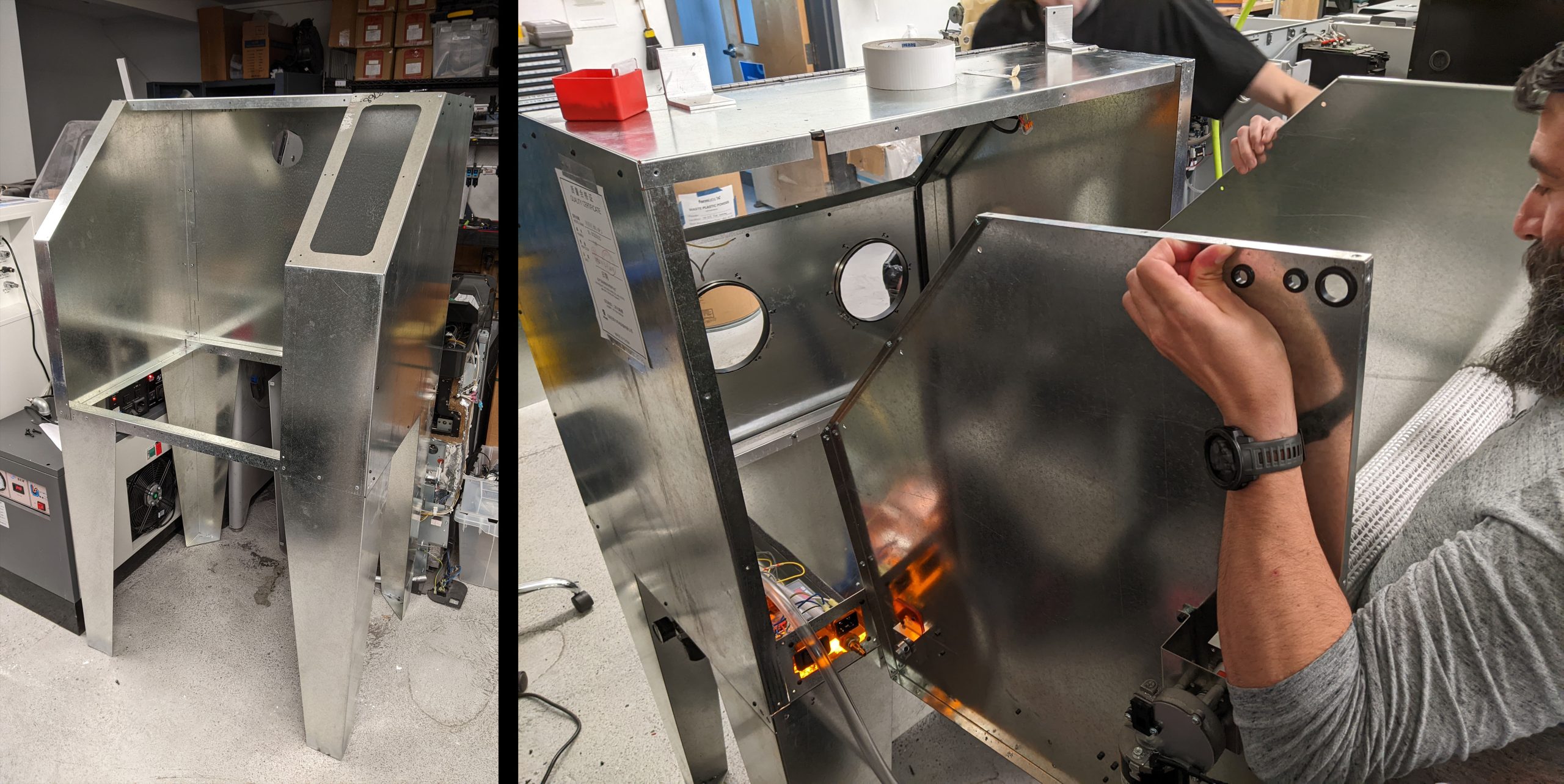
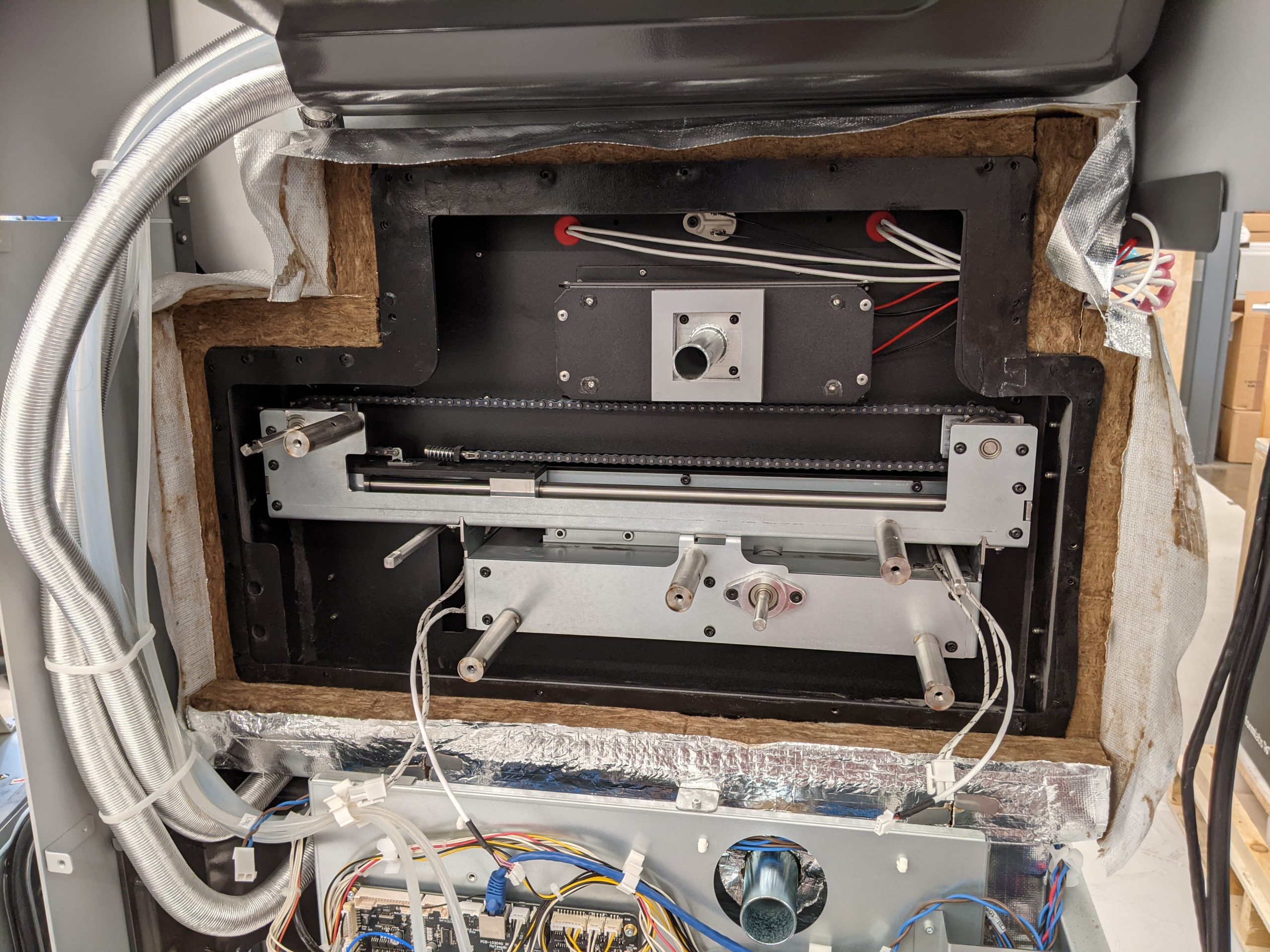
I then led the design for the first fully custom prototype
I designed all parts except for the media hopper and filtration system
All sheet metal was ordered from OSH Cut for fastest manufacturing and low cost
The belt system was designed as a standalone unit that slides into the back of the machine
Assembly of First Prototype
Finished First Prototype
Prototype used heavily for experimentation on part cleaning performance and user experience
The design worked, and had a significantly improved user experience over a manual blast cabinet
Integrated Belt Tumbler
Additional Belt Prototype
I created one more belt tumbler prototype with a single piece rubber belt to compare performance
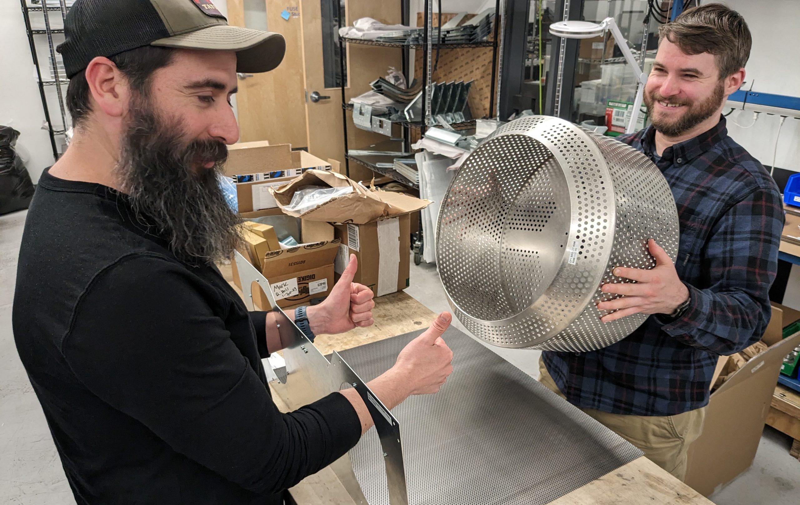
The second full machine prototype was designed with a basket-style tumbler
I continued leading the CAD architecture for the next prototype, which was planned to be a full works-like prototype with multiple huge improvements
First Parts of Second Prototype With Basket Tumbler
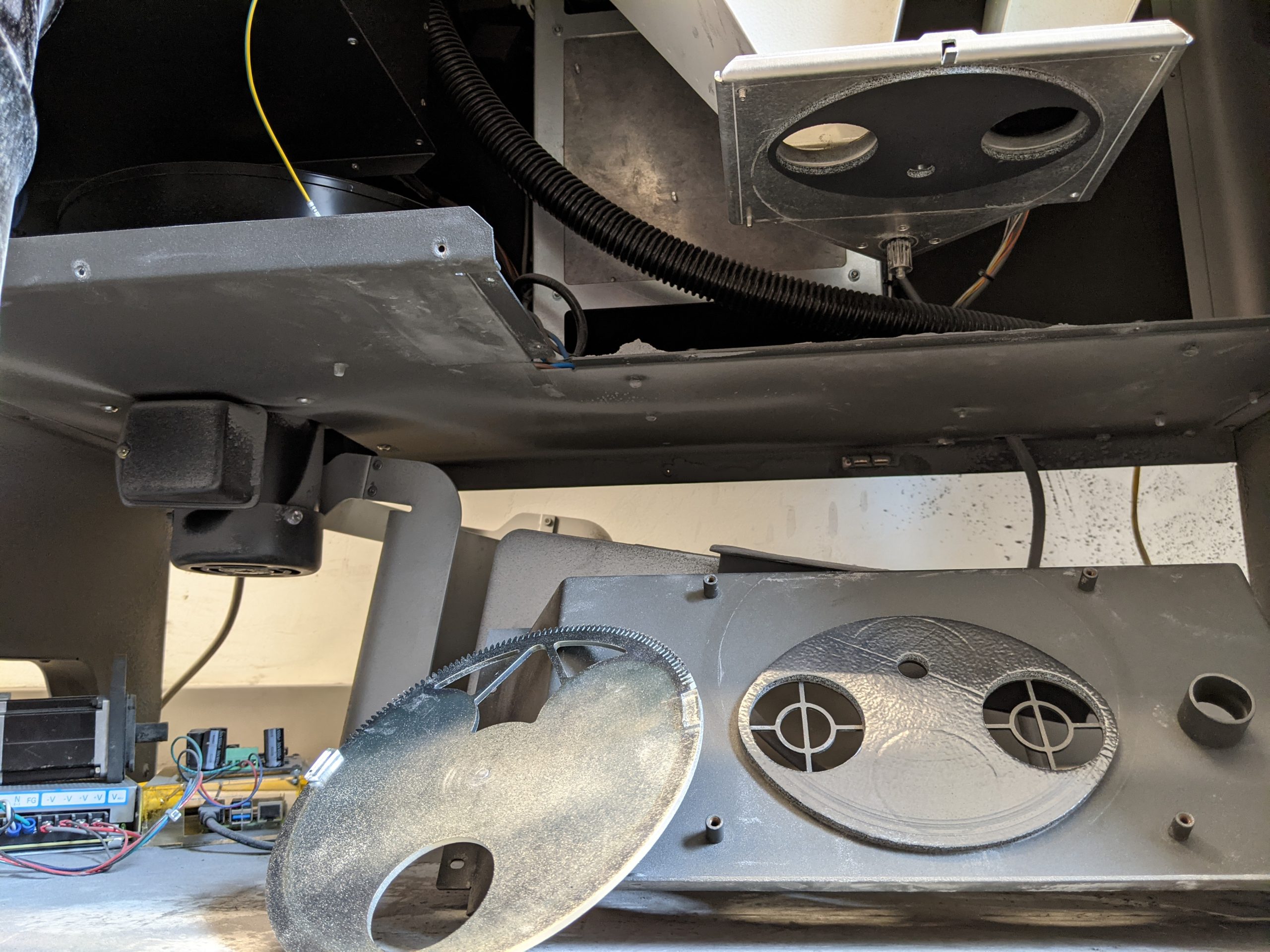
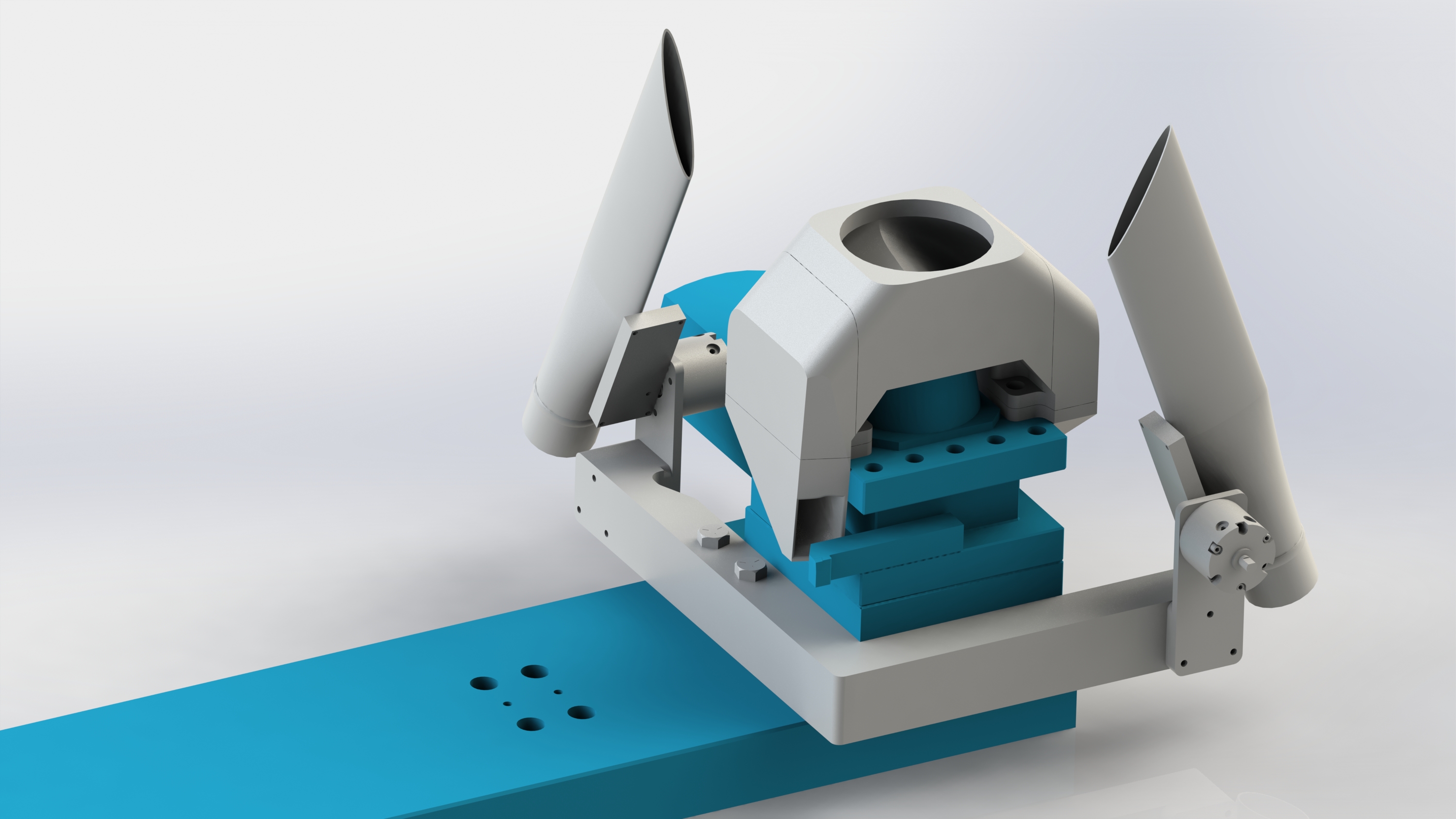
Door Gas Spring Operation
I still designed all sheet metal structures and shells
Created a spreadsheet calculator to design the gas spring kinematics. The design worked perfectly on the first try
• Finished works-like prototype shown
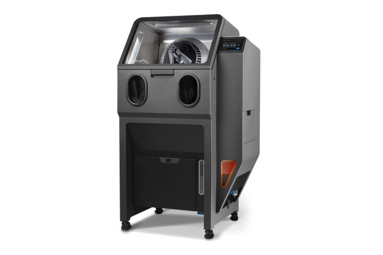
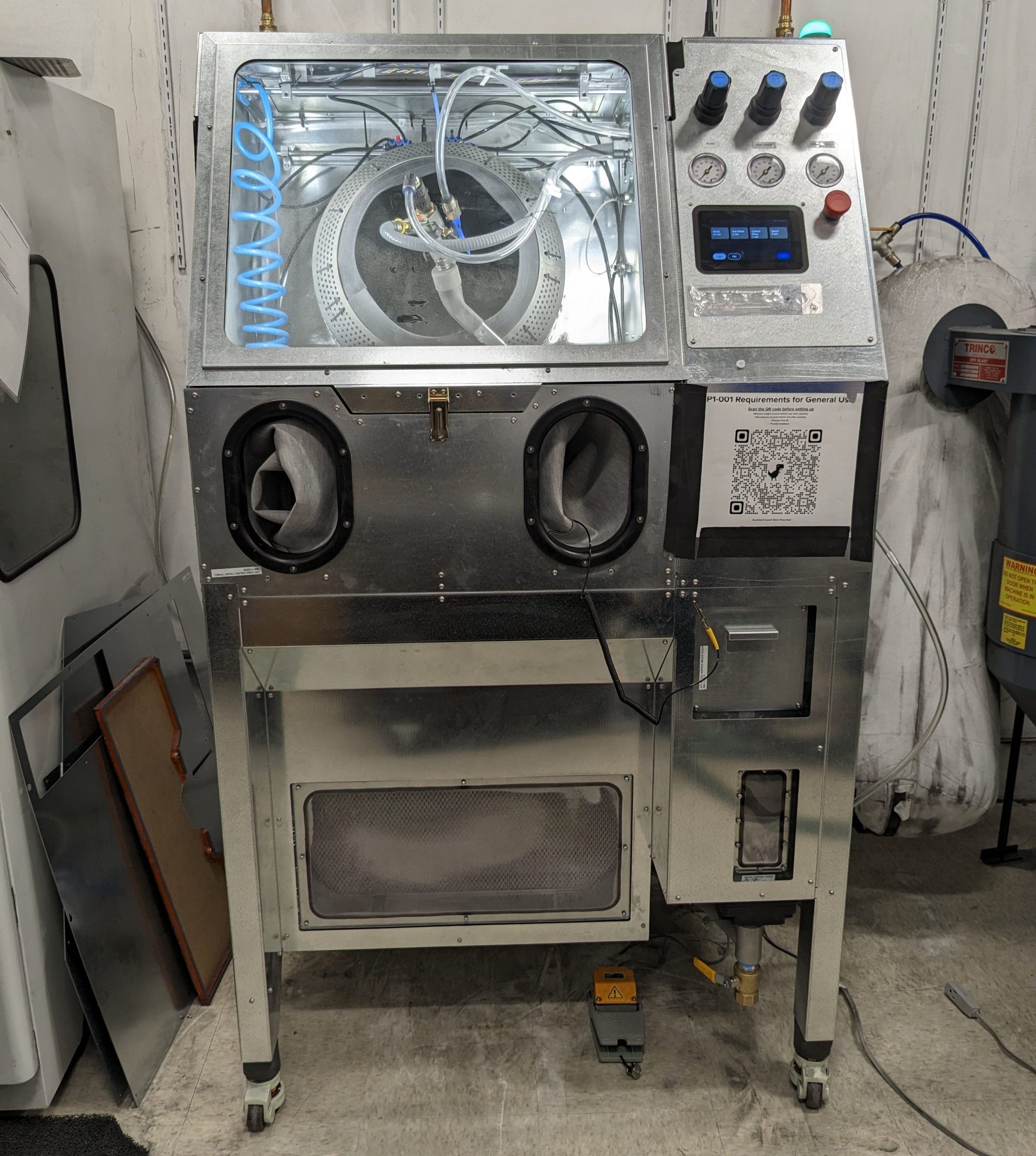
Finished Second Prototype
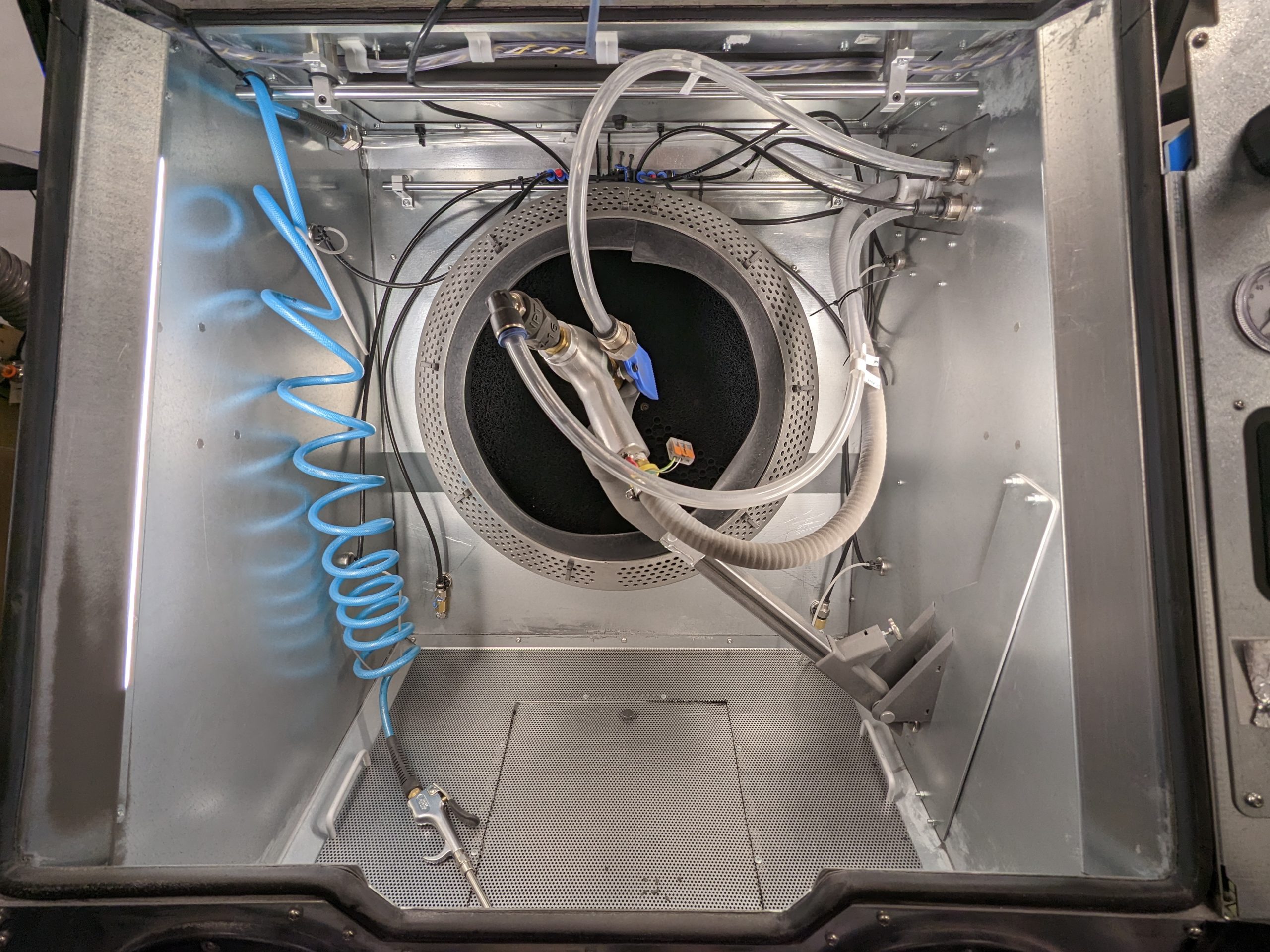
Inside Blast Chamber of Second Prototype
Some variables were fixed such as the lighting and basket position, but significant experimentation continued with the media blast and air rinse design
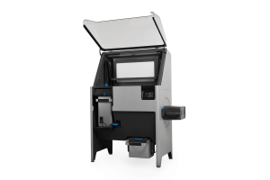
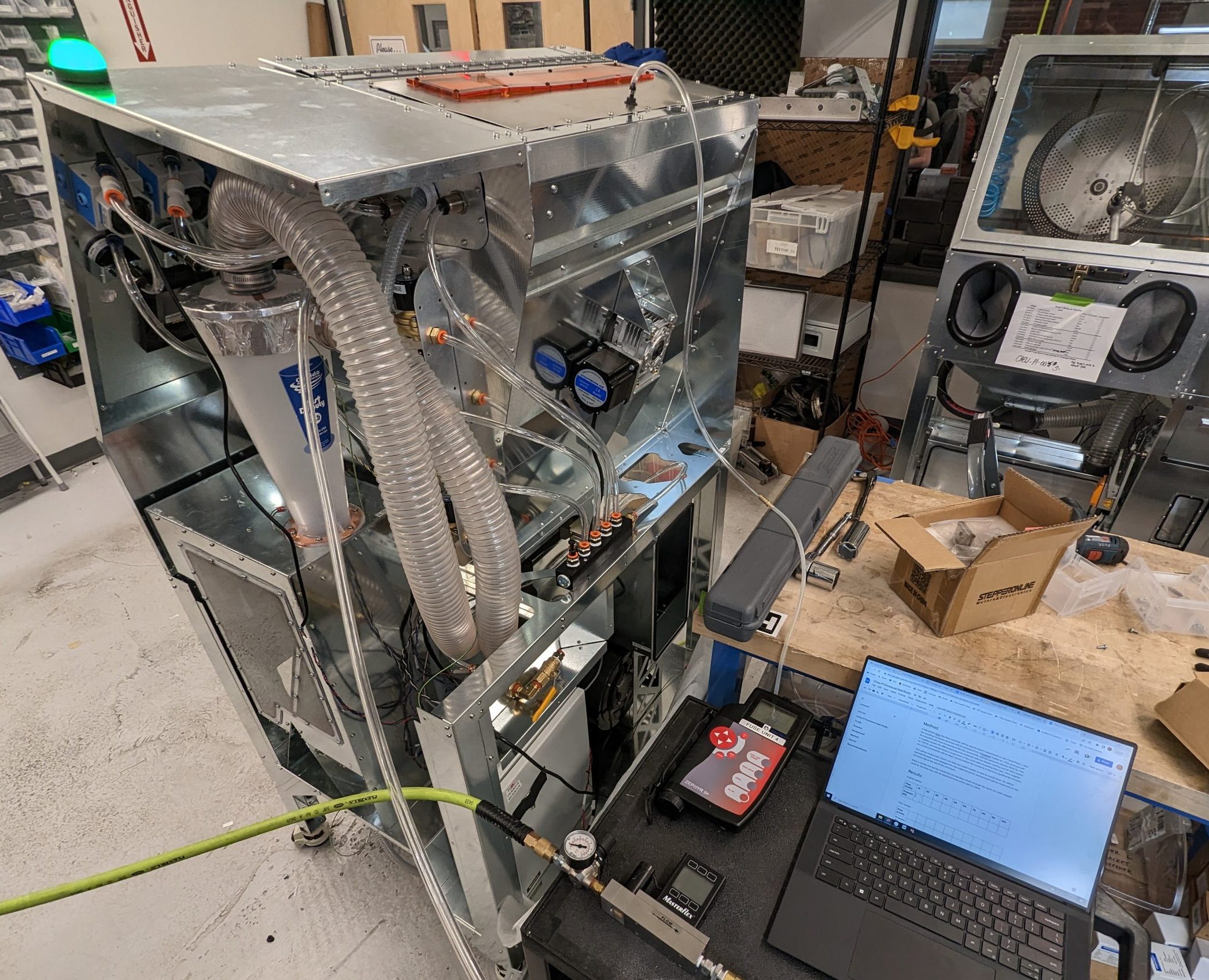
A significant change was with the air handling and media filtration systems. The previous prototype simply used a vacuum for dust extraction and gravity for media transport. This prototype integrated dust extraction into the machine, and used it to dual purpose as a pneumatic media transport system
This prototype met the target performance requirements so we moved on to designing the full works-like, looks like machine
Air Handling System for Second Prototype
Door Latch Testing for Third and Final Prototype
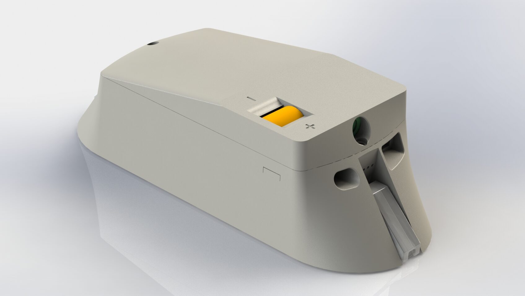
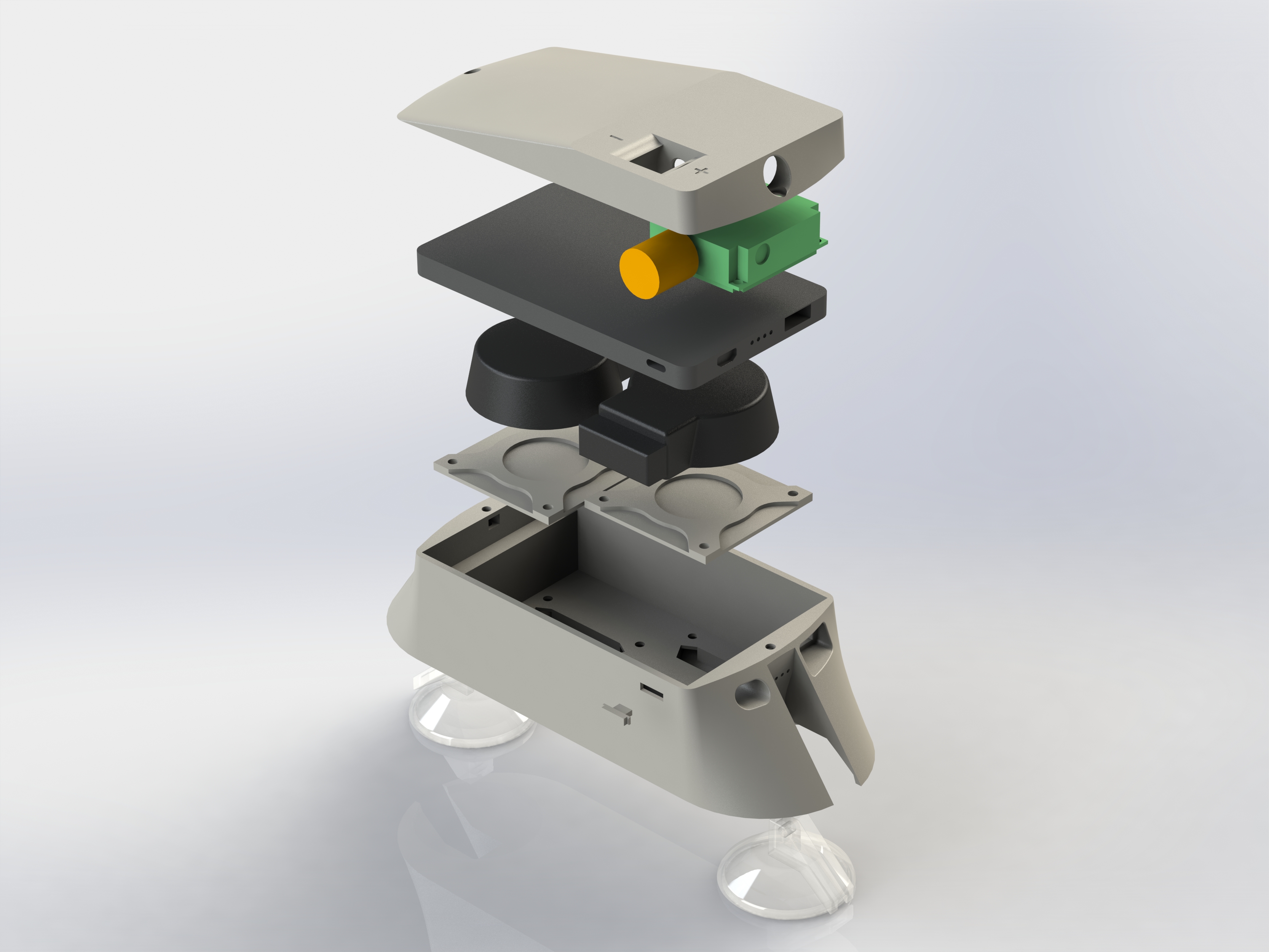
I remained the CAD lead for the final prototype. It was intended that this was the final design that would eventually ship to customers with a few tweaks, so I used everything we learned from the previous architectures to make it as robust as possible
I worked closely with the industrial design team to help choose the aesthetic layout that was the most reasonable for manufacturability
I designed the layout for subsystem space claim, and convinced the team to make a few changes from the previous prototype to be more compact and improve access to the media hopper
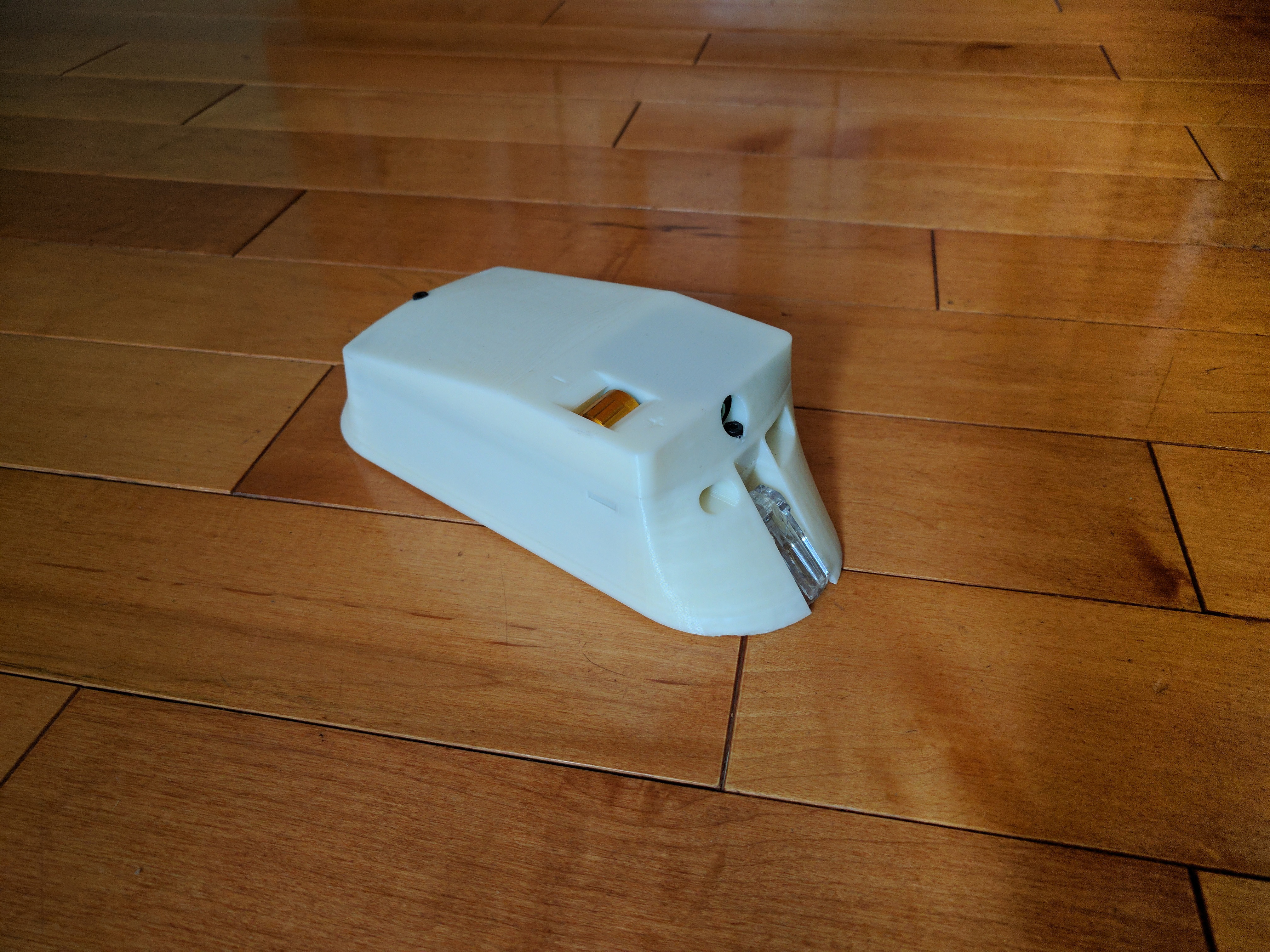
A tricky part to design was the main door latch. The ID team drew up an aesthetically sleek latch, but I had to figure out how to make it function. I made a prototype door to test several latch designs
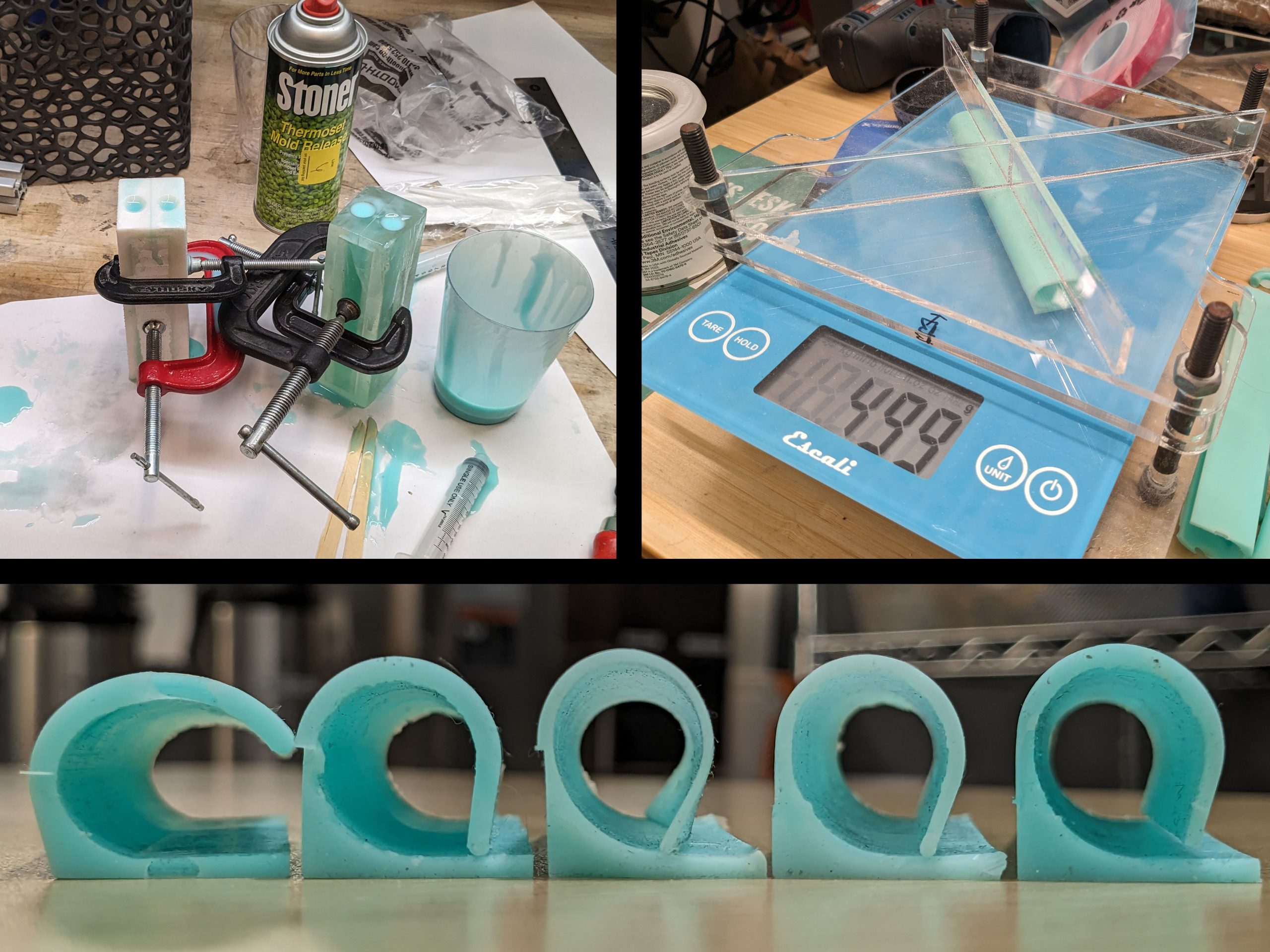
An additional issue was with the main door gasket. The original plan was to use an extruded foam profile, however there were some issues with this design
I got a rough quote for a single-piece compression molded gasket and the price increase was only a few dollars, which was determined to be worth the improvement in quality
I iterated prototype molded sections in-house to dial in the compression force before ordering tooled parts. Needed to be low enough force for manual door latching, but high enough for reasonable sealing and interlock triggering
Door Gasket Prototypes for Compression Molding
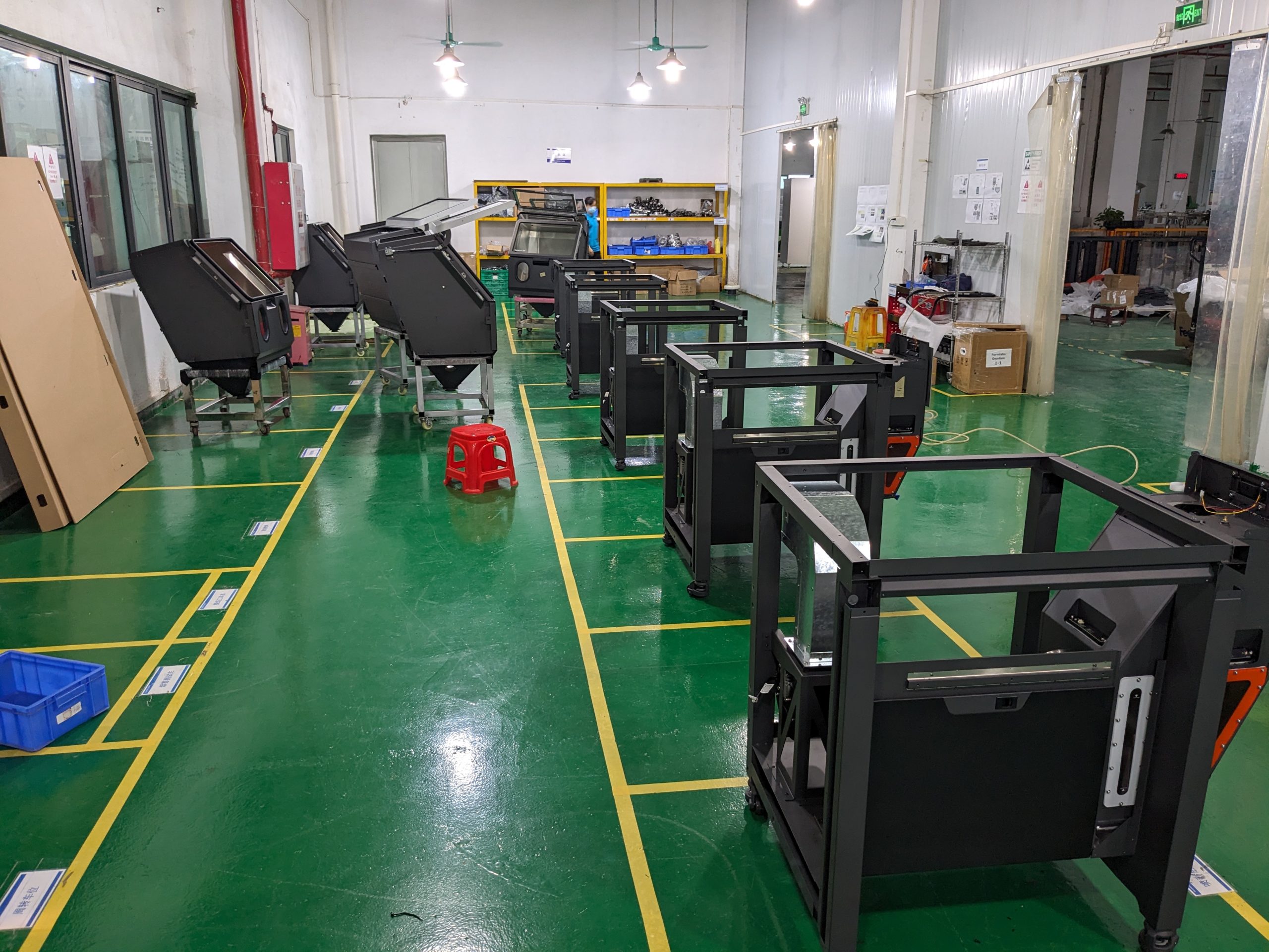
Final Assembly Line in China
To follow the tight timeline for this final prototype we had all the parts made directly in China and assembled at the factory for the first build, then air freighted back to the US for inspection
Despite a bit of chaos these first builds were fully functional
Shown is the final assembly line. I designed the sealed blast chamber to be a standalone assembly for easier seal testing, which then drops on top of the base assembly
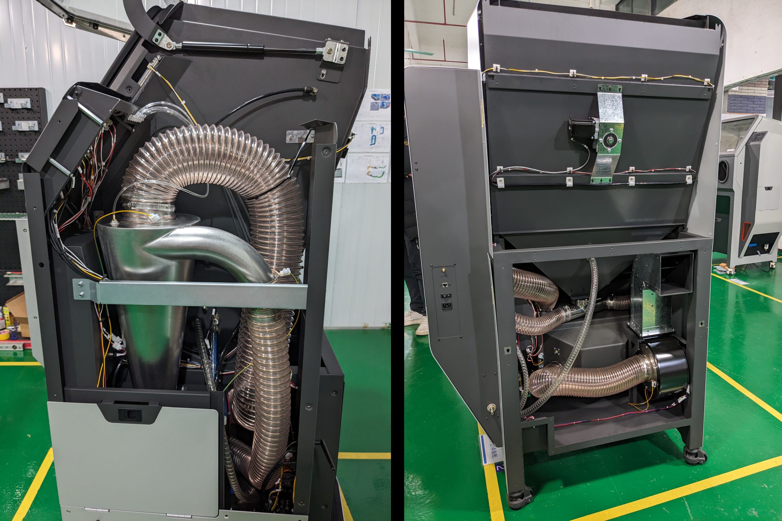
The pneumatic media conveyor system is shown
It is much quieter and more effective than traditional blast cabinet dust extractors, and we were able to fit it inside a compact form-factor
Interior of Final Design
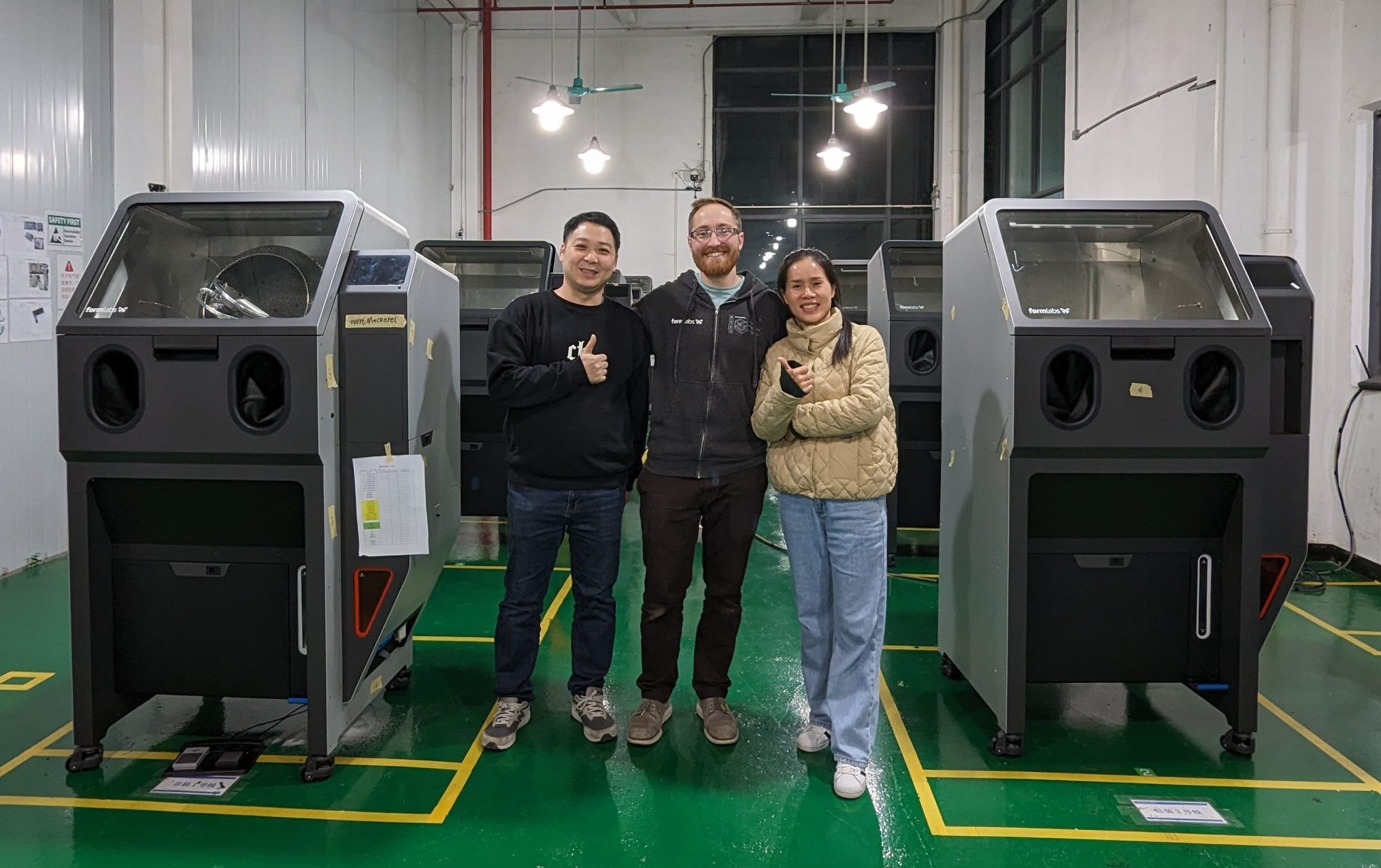
Me With First Customer Approved Machines
Thanks to the help of our China based manufacturing engineer and factory representative I was able to approve the first units for shipment to customers
The product launch was a success. Fuse Blast retailed at 1/3 the cost of closest competitor, and was the highest revenue Formlabs printer accessory in 2024
2021
Fuse Sift Improvements
Original Sift Doser (Left) and TPU "Rope" Debris (Right)
In 2021 I became the responsible engineer for Sift to work on a few improvements before ownership was transferred to the sustaining engineering team
The main issue was with the powder dosing mechanism, called the “doser.” This sits at the bottom of the machine and controls powder flowing from the used and new powder hoppers into a cartridge at the desired ratio
The launch of TPU powder for Fuse 1 was blocked because of incompatibilities with this subsystem
The steel rotary gate is sandwiched between a delrin plate and a foam gasket with UHMW film to reduce friction
This prototype solved the problem, but the hard part was sourcing the correct foam from China and lifetime testing it with all types of SLS powder to properly validate the hardware change and mitigate risk
Redesigned Doser Stackup for TPU Compatibility
3D Printed Powder Screw to Automate Lifetime Test
The lifetime test had only previously been completed once before and was done by hand, taking several days of filling cartridges and dumping them back into the machine (~4500 kg of powder total), so I had to automate this for reasonable iteration time
The first design was to use a flexible 3D printed screw to recirculate powder
Even with multiple design iterations the nylon screw simply couldn’t handle the fatigue life of a full 25 hour test. Possibly using multiple straight screws could have worked better but this would have increased complexity
The next simple option included using a vacuum with cyclone separator we already had on hand with a spring loaded base to dump powder when full. This worked at first however the gasket degraded over the course of the test from shear loading, reducing the cyclone efficiency and eventually pulling all the powder out of the system
A third option was to use a diaphragm pump to fluidize and push powder, however it was very finicky and stalled often
Finally the cyclone separator was re-visited and a new base was designed with a significantly improved gasket that would not wear out. This design worked well enough to complete the remaining lifetime tests
I created a python script to run the lifetime test on Sift, control the vacuum, monitor the powder level, perform stall current checks, and log data
My TPU compatible doser was lower cost with a longer lifespan than the original, and was approved
Alternate Setups Tested to Recirculate Powder
Formlabs Misc Projects
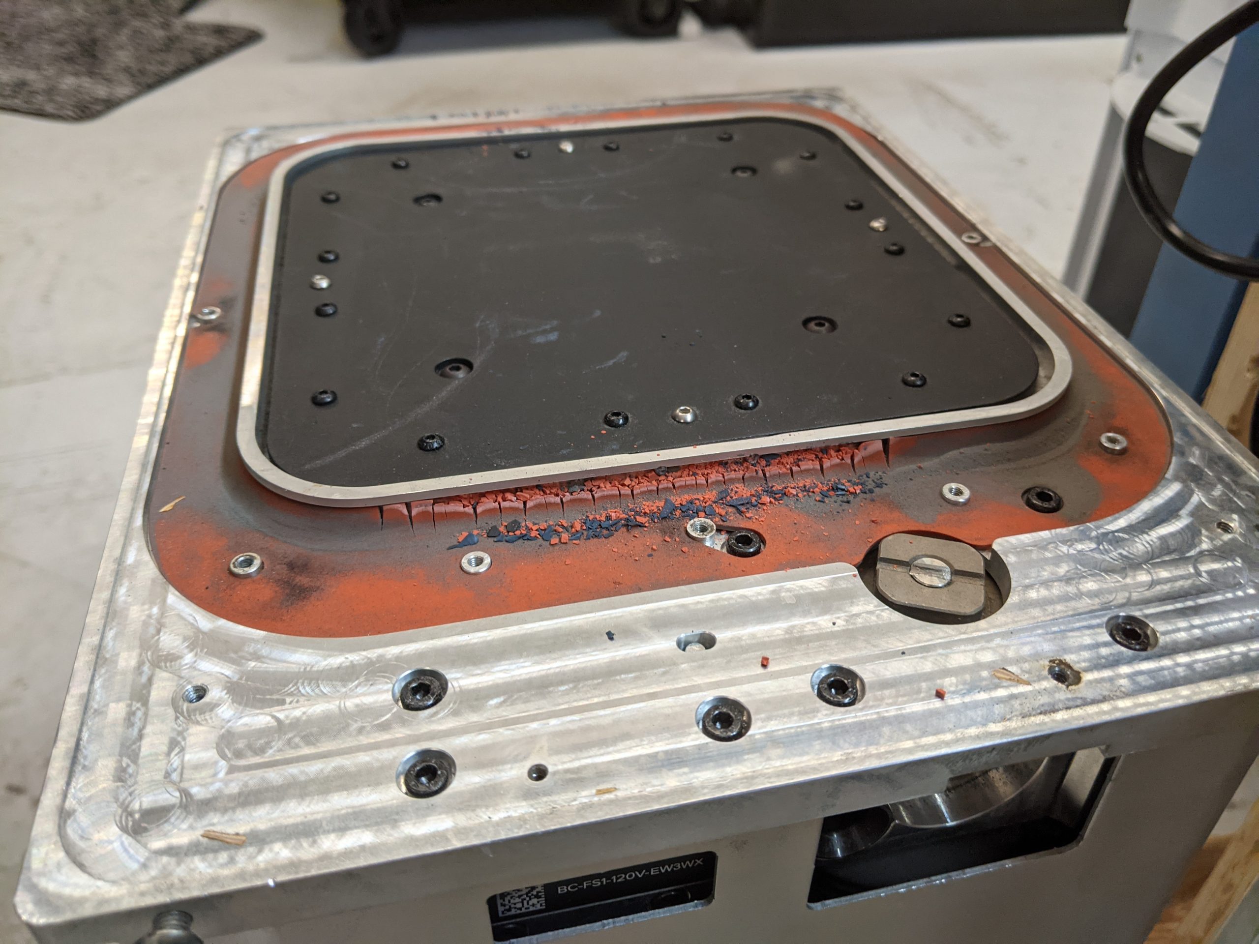
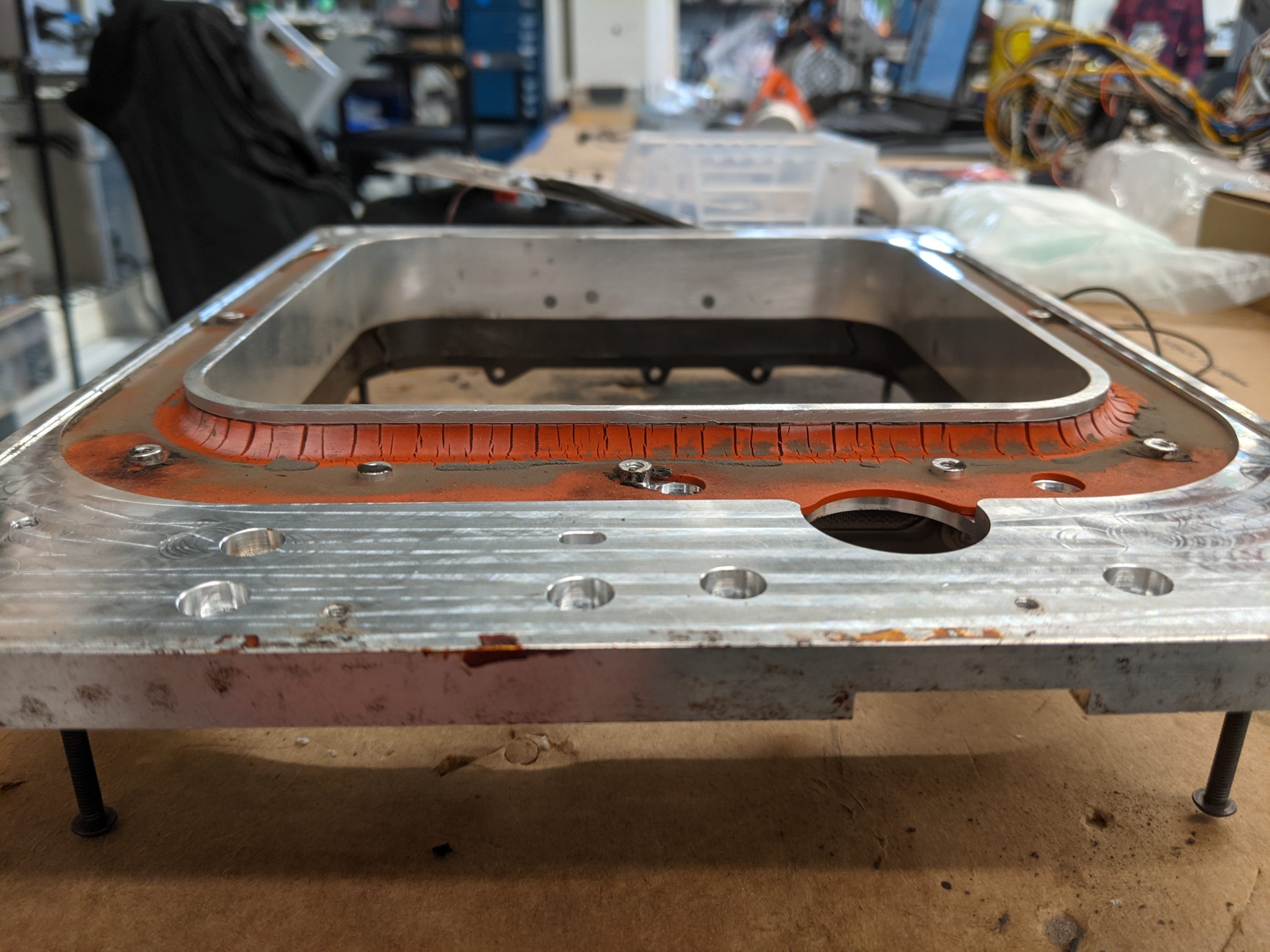
Degraded Gasket on Fuse 1 Build Chamber
An issue was discovered with the Fuse 1 Build Chamber where a gasket was consistently degrading well before the expected lifespan, causing powder leaks
A few different engineers investigated the issue but were not able to root-cause and find a good solution
After a few attempts I was able to replicate the failure mode with an accelerated lifetime test
Replicated Gasket Degredation
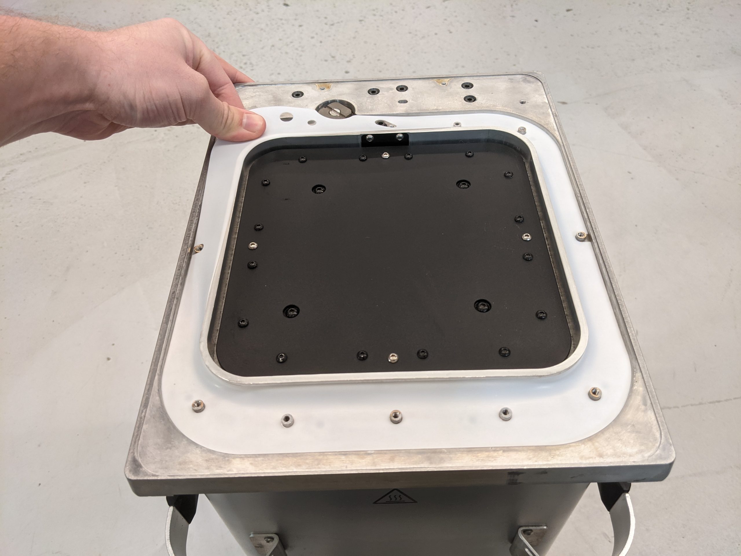
Issue Solved with Alternate Gasket Material
Multiple alternate materials were tested and I found the lowest cost alternative which sealed equally well but without the same failure mode
Validated samples from Chinese supplier, implemented solution and worked with the services team to create a customer replaceable part package with instruction guide
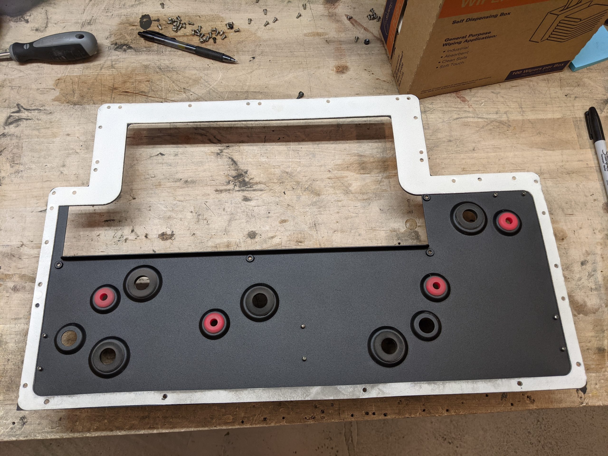
Another costdown was for a few large perimeter gaskets on Fuse 1. These are expensive high temperature silicone foam gaskets that are die-cut in a single piece, which wastes all the material cut out from the interior
Expensive One-piece Gasket on Fuse 1
Cost-down Gasket Made From Three Sections
I sourced samples in a lower cost material and worked with the manufacturer to create the gasket from three separate pieces with dovetails
Installation was initially much more difficult due to the new material having lower tensile strength, but fortunately I knew my way around the 3M catalog and was able to select a double sided adhesive with a much more supportive carrier, solving the issue
Performed seal and temperature checks to validate performance
Gasket changes saved over $50 per printer, or around $50,000 per year
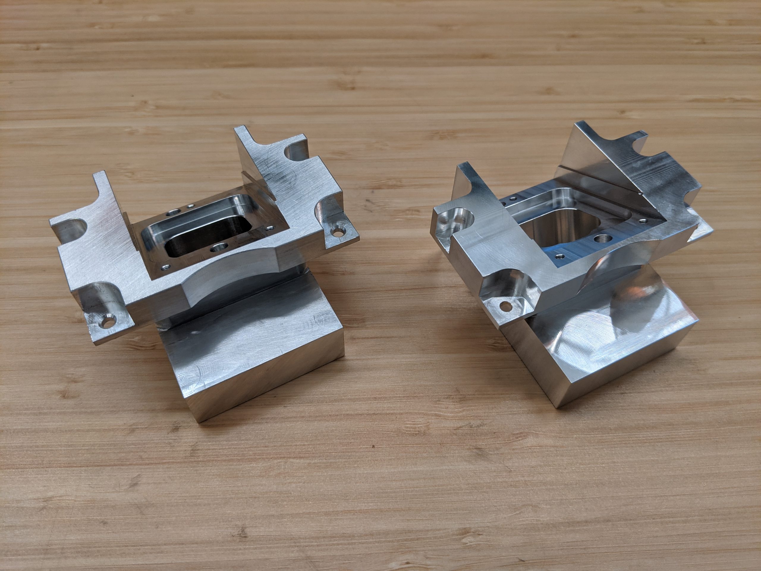
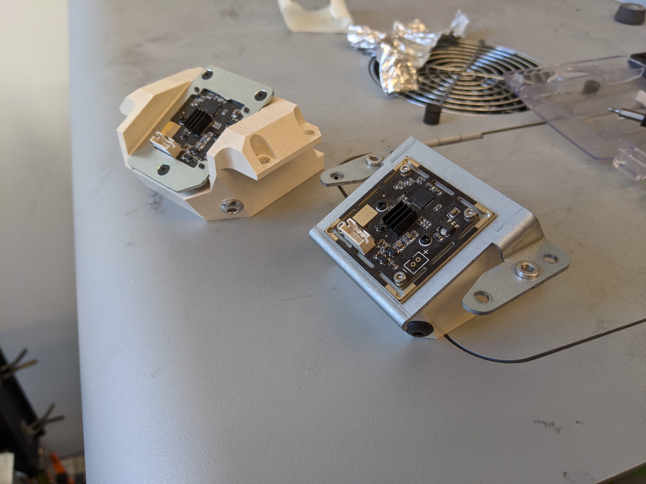
An additional costdown was made from revisiting the Fuse 1 camera mount I designed below
The original part was machined from PEEK to reduce thermal conduction from the print chamber, however this was very expensive
A silicone gasket below the mount was already doing most of the insulation, so machined aluminum was theorized to be an acceptable replacement for PEEK at a much lower cost
I redesigned to reduce the number of machining operations, validated the change with thermal uniformity testing similar to below, and implemented the change
Saved an additional $20 per printer, or $20,000 per year
Cost-down Fuse 1 Camera Mount
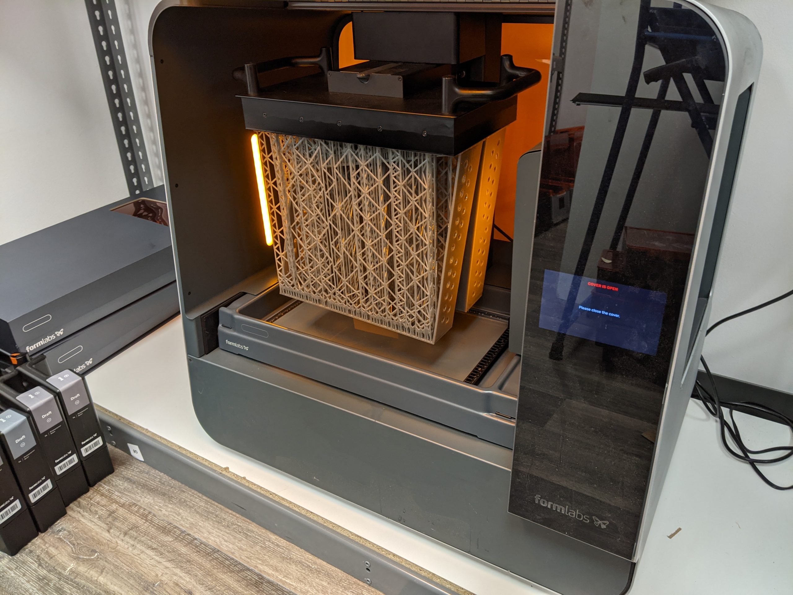
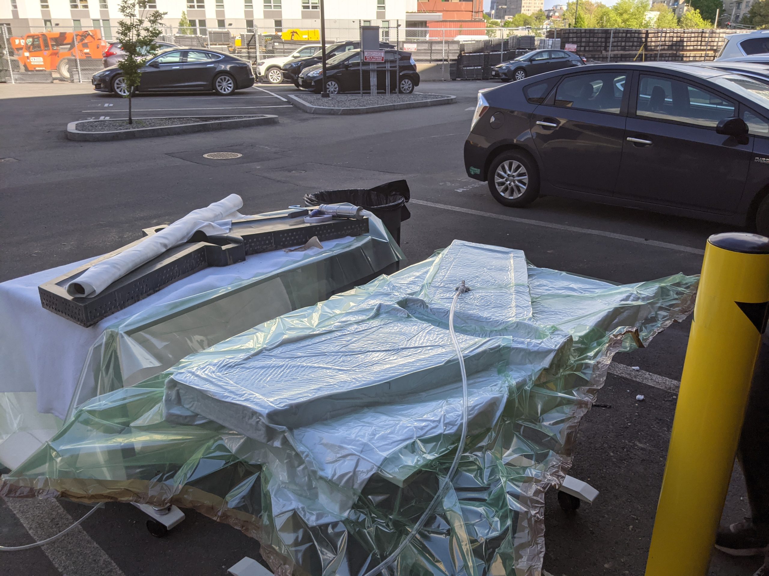
Composite RC Flying Wing
Printed Sections of Composite Wing Mold
Formlabs hosted a hackathon every year to allow all employees to work on any project they want for three days, ideally 3D printing related
Myself and two others with RC aviation experience set out to make a composite RC plane directly with 3D printed molds
The conventional mold making process takes significant time and skill, but 3D printing has the capability to change that
Aerodynamic design chosen with XFLR5 software, CAD with Onshape and printed in several sections on Form 3L with Draft resin
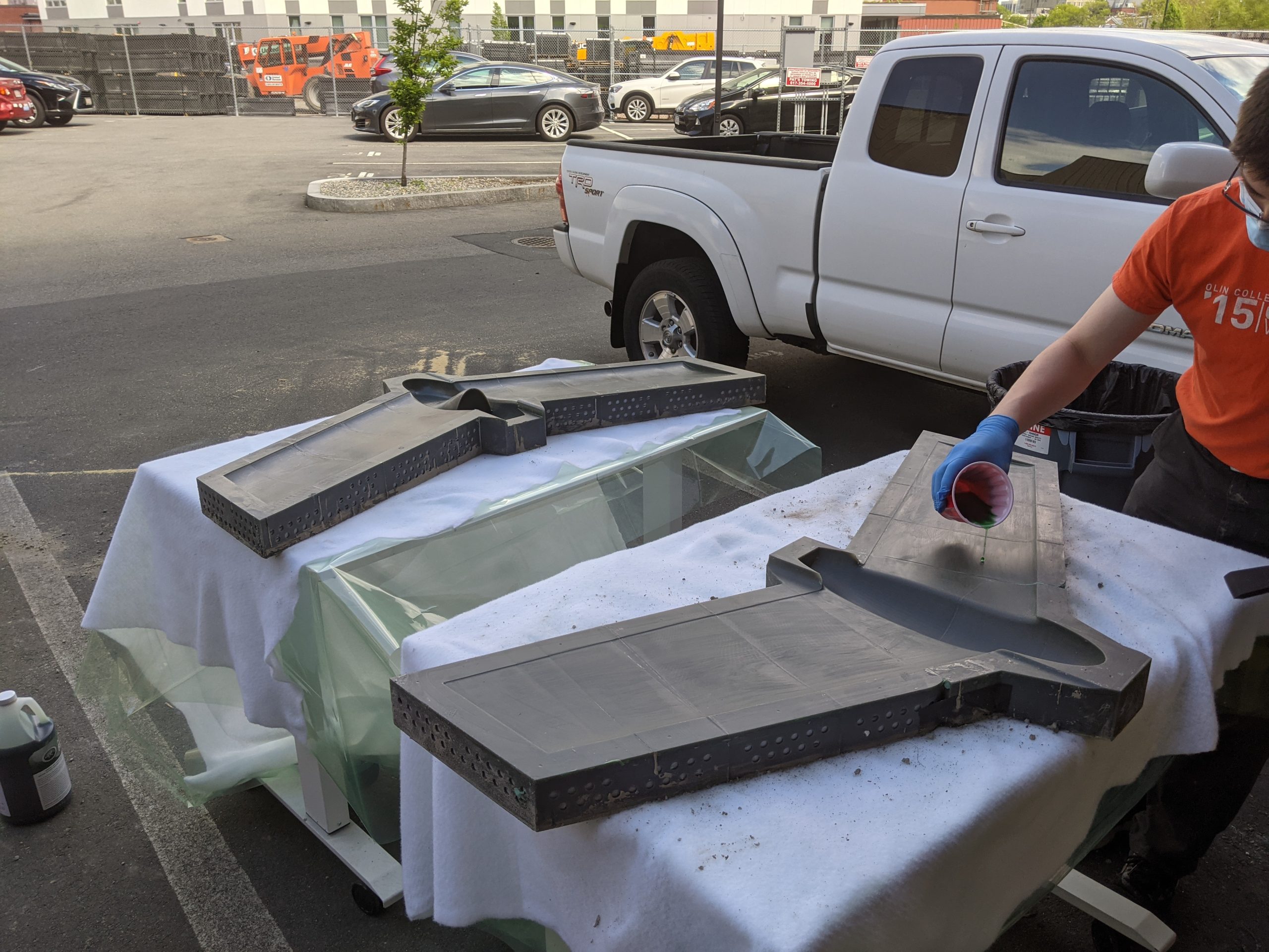
The molds were assembled and coated with PartAll paste and PVA
Mold Halves Coated with Wax and PVA
Vacuum Bagged Fiberglass
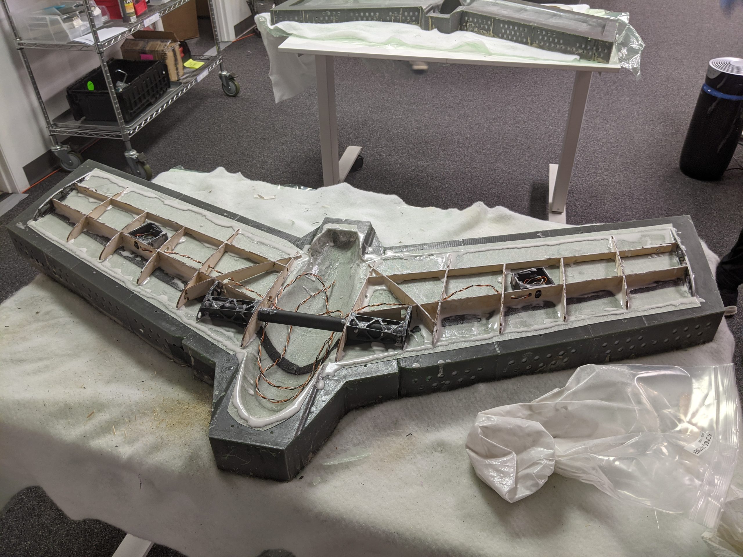
The fiberglass, epoxy resin, and carbon strip were vacuum bagged in the mold
Balsa ribs were lasercut and glued in place
Spar caps, servo trays, and winglets were 3D printed on Fuse 1
The three days of hackathon ended with the project at this state so the team shelved it for next year
Internal Structure Glued in Place
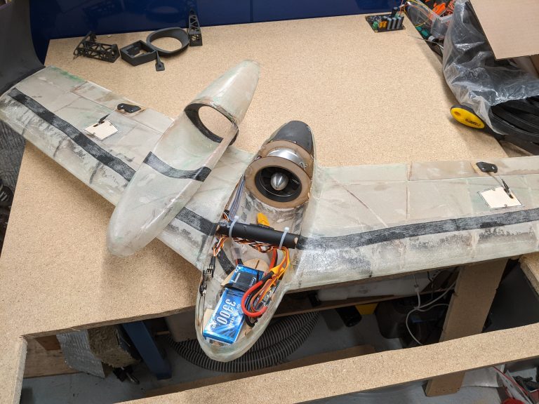
RC Plane Ready to Fly
During the second hackathon we finished building the plane
It was test flown but couldn’t be hand launched fast enough and stalled on each launch attempt
For hackathon year three I built a bungee launch cart and it flew! Unfortunately however the flight was short, I was almost able to circle a full lap but it appeared to tip stall and crashed into the woods. We decided to move on from the project after that
2020
Formlabs Initial Projects
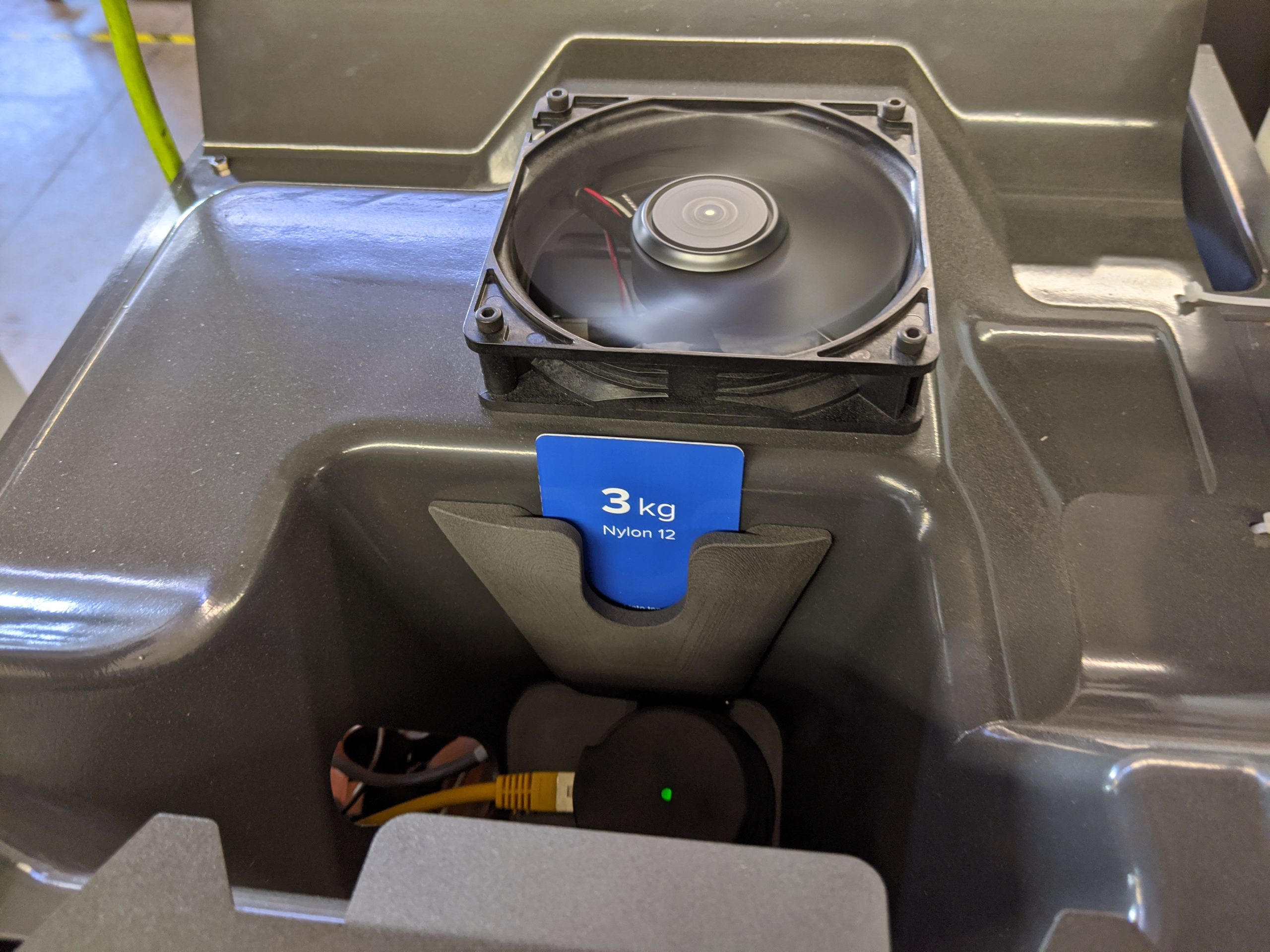
Prototype IM Part on Fuse 1
A subset of initial projects I worked on at Formlabs in 2020 are shown. This work began about 10 months before the Fuse 1 printer started shipping to customers
One initial project was to turn a few roughly prototyped parts on the machine into production-ready injection molded parts
These were my first parts designed for injection molding
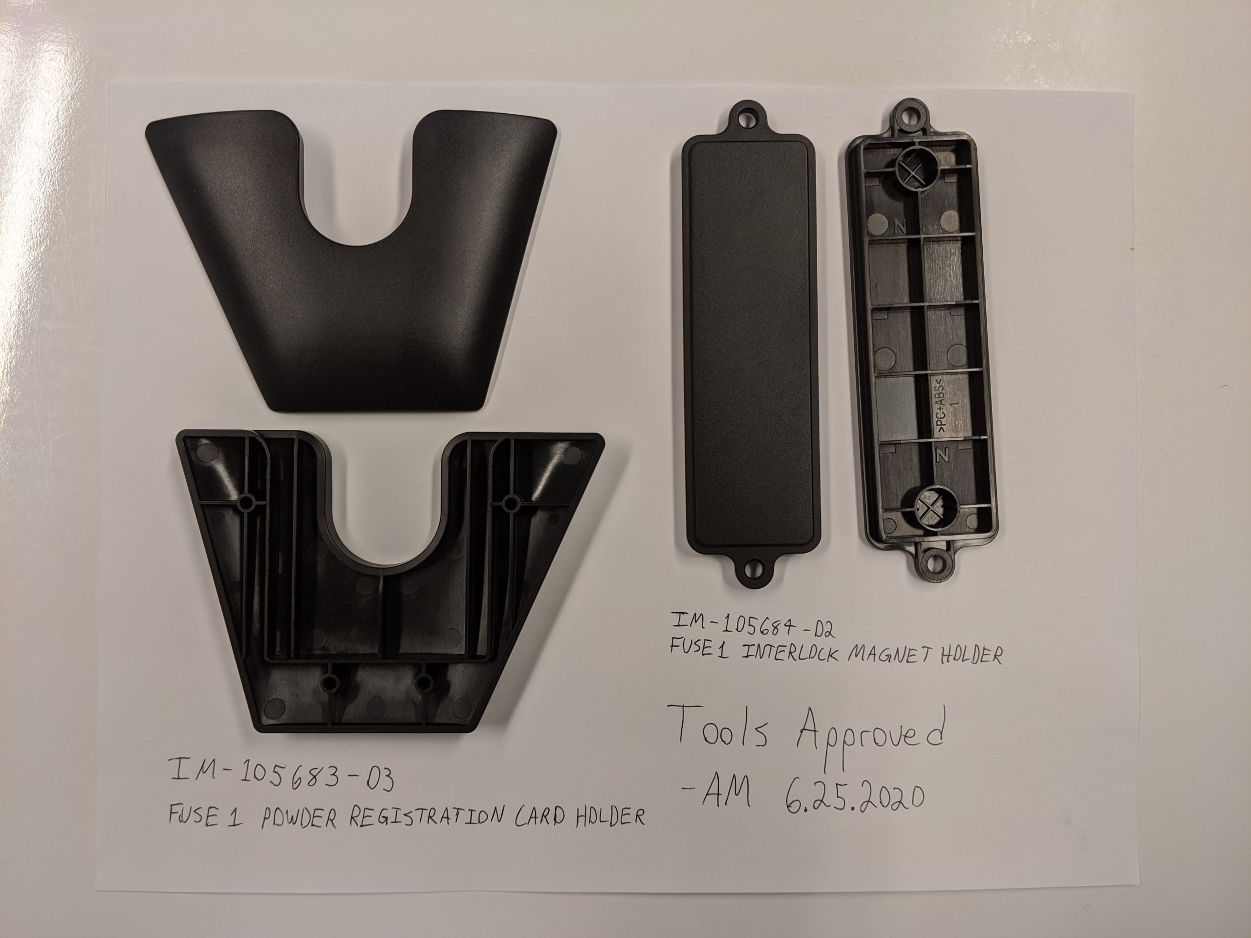
Parts included bosses for thread forming screws, crush ribs for press-fit magnets, and mold texturing
Communicated constantly with industrial design team and Chinese manufacturer to get successful parts on time
Approved IM Parts for Fuse 1
Redesigned Camera Assembly
The camera on Fuse 1 allows the user to view the print area as well as computer vision to monitor print success
The camera is required to be adjusted slightly in pan and tilt during printer assembly
The original design (right) was difficult to manufacture, difficult to adjust alignment for, and sealed poorly
I redesigned the mount to fix all of these issues and even reduce overall cost (left). Further costed down above
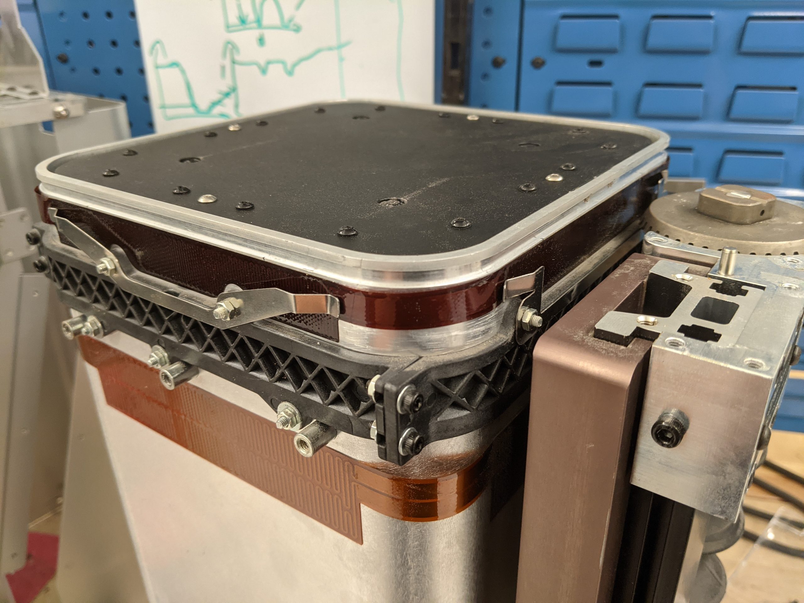
The build chamber on Fuse 1 contains the parts as they are printed and lowers the piston top in Z to create each layer
There were issues with the adhesive backed build chamber wall heaters peeling off after thermal cycling
The adhesive process could not be improved, so I designed low cost clamps with little increased complexity to assembly
Build Chamber with Added Heater Clamps
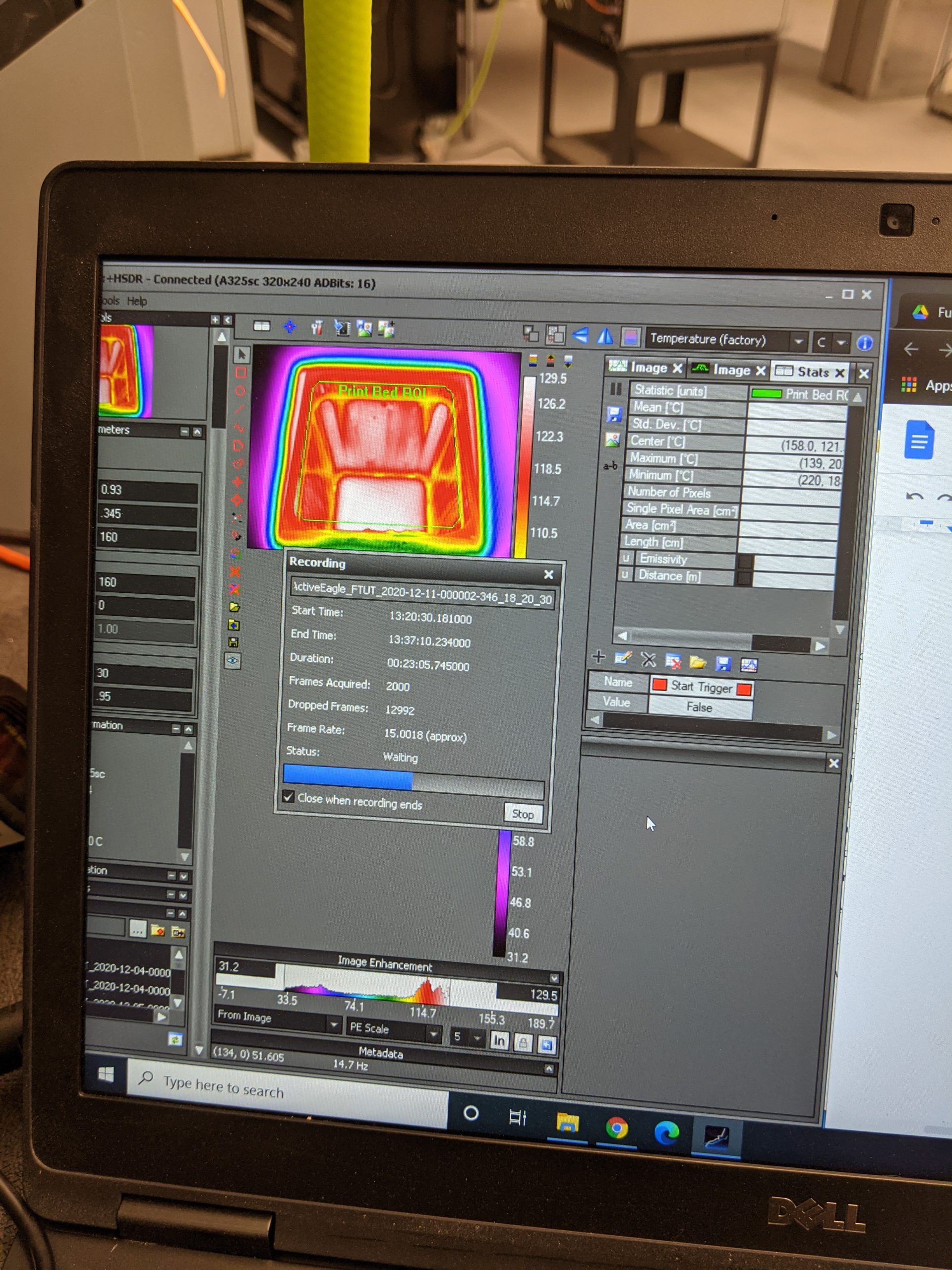
Thermal Uniformity Test
All changes that could impact thermal uniformity of the print area required standardized AB testing to assess impact
This testing was done for the heater clamps before approval to ensure no unexpected heat transfer was occuring
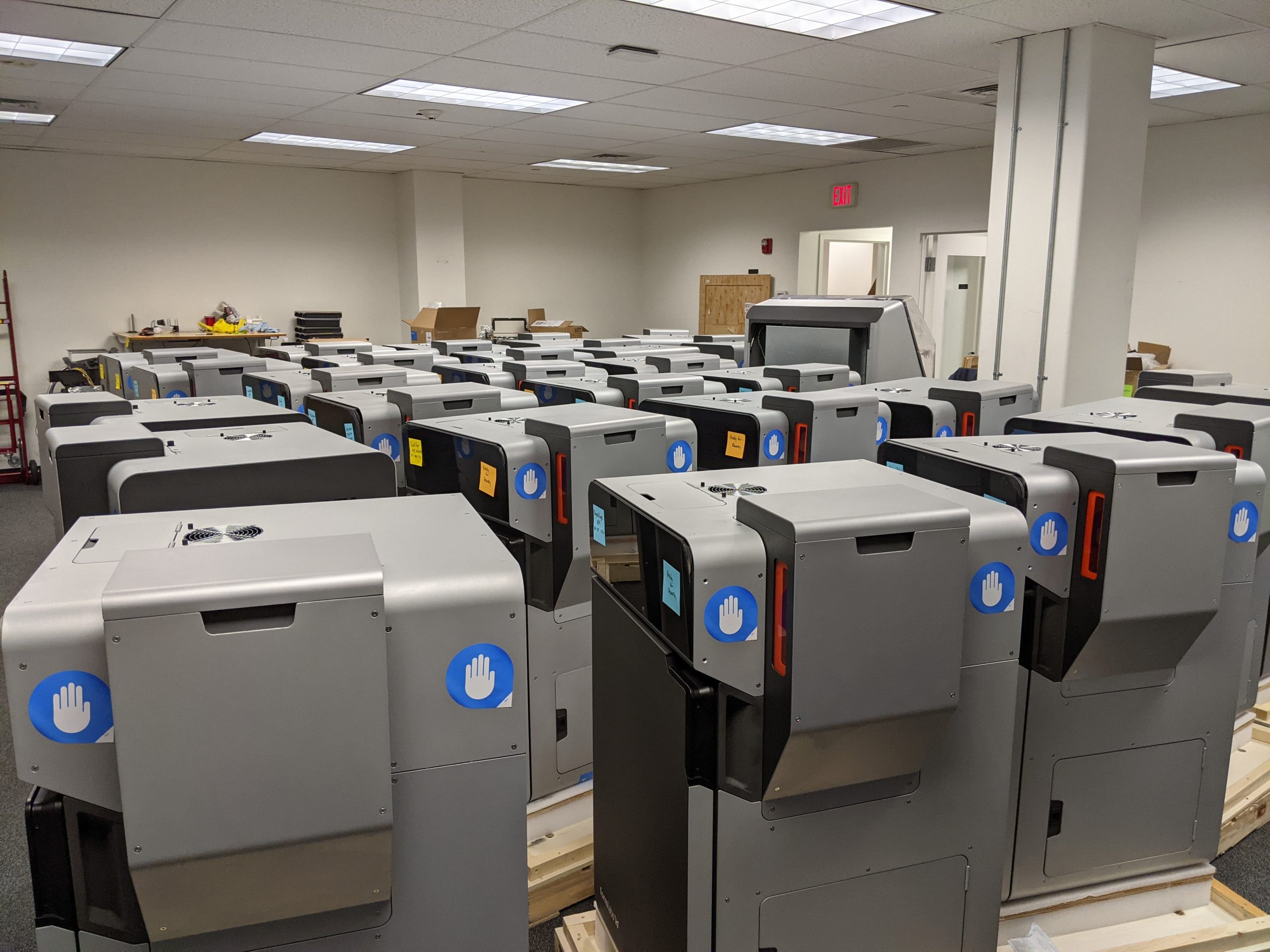
Batches of builds were completed in increasing quantities during the ramp to mass production to catch issues that arose with increased production and give engineers time to address the issues and validate solutions
Printers were sent to Formlabs HQ before going to beta customers or the warehouse
I helped inspect printers and ran factory calibration tests to confirm printer quality
Incoming Quality Control Before Launch of Fuse 1
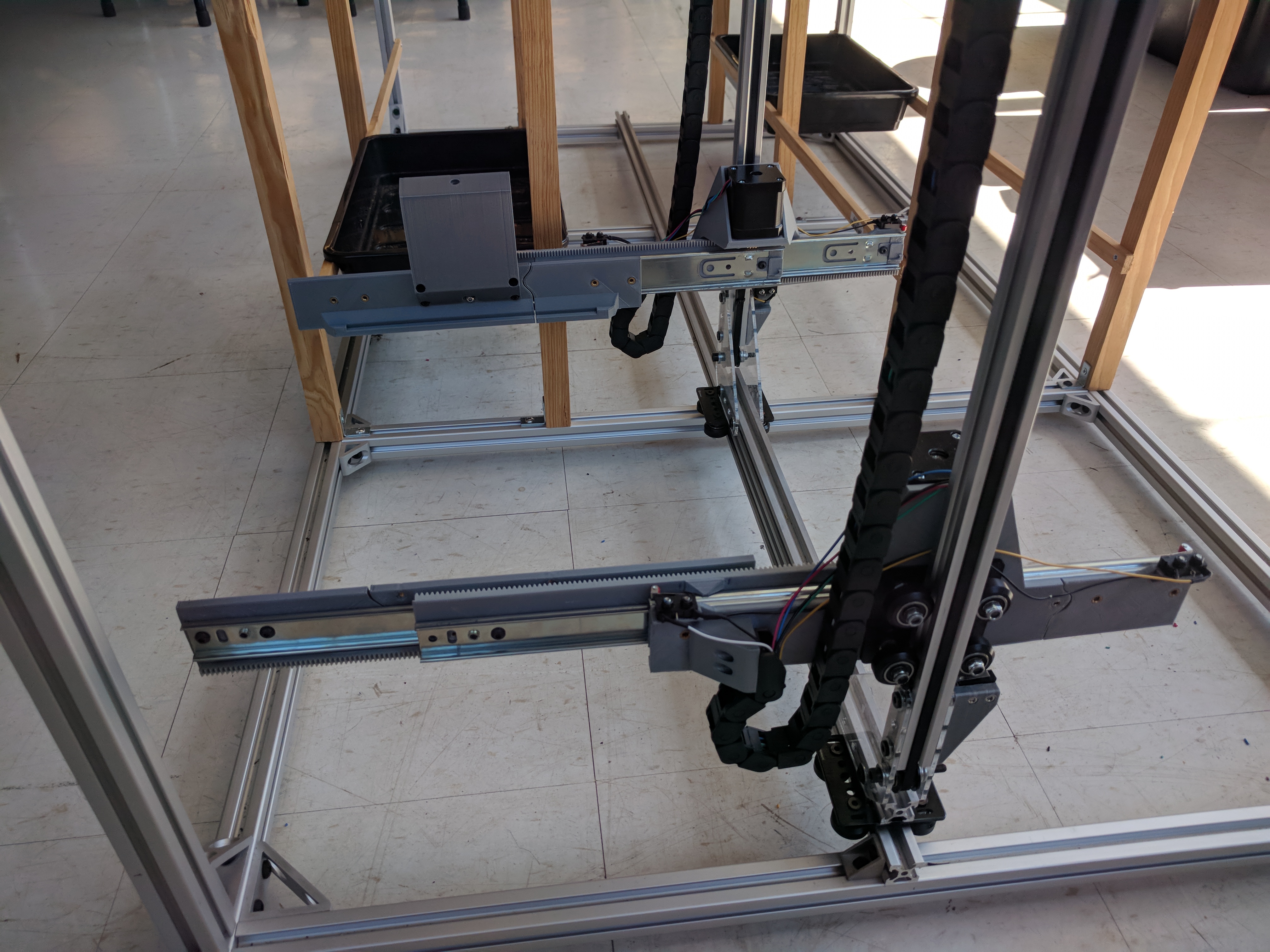
Automated Hydroponics Full Scale
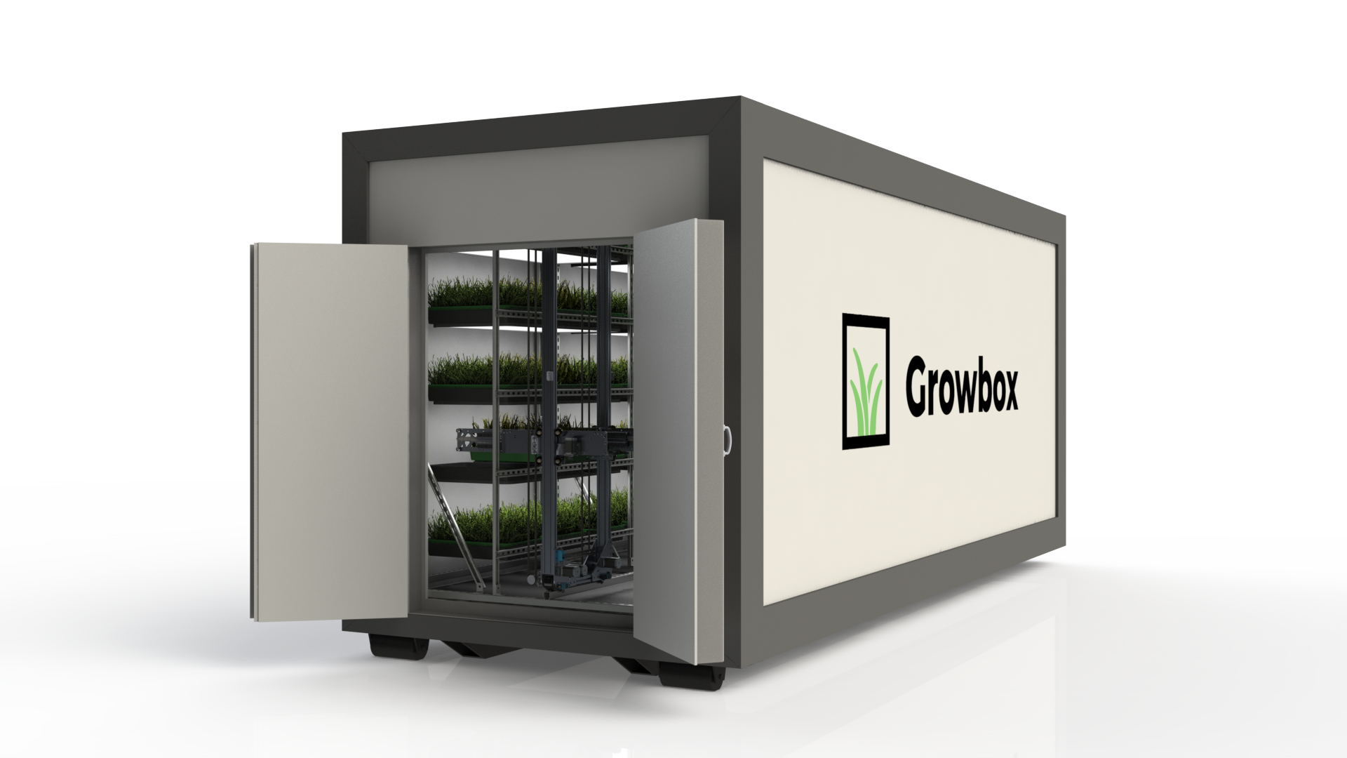
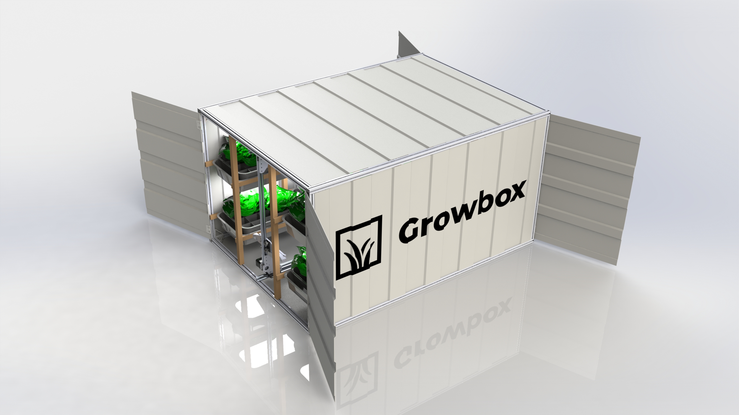
Full Scale Growbox Exterior Render
Building off the concept for the small scale automated hydroponics prototype below, I designed a full scale prototype for Growbox
The concept includes a base compatible with standard roll-off containers for easy transport, SIP panels for low cost insulation, and steel strut channel for internal structures
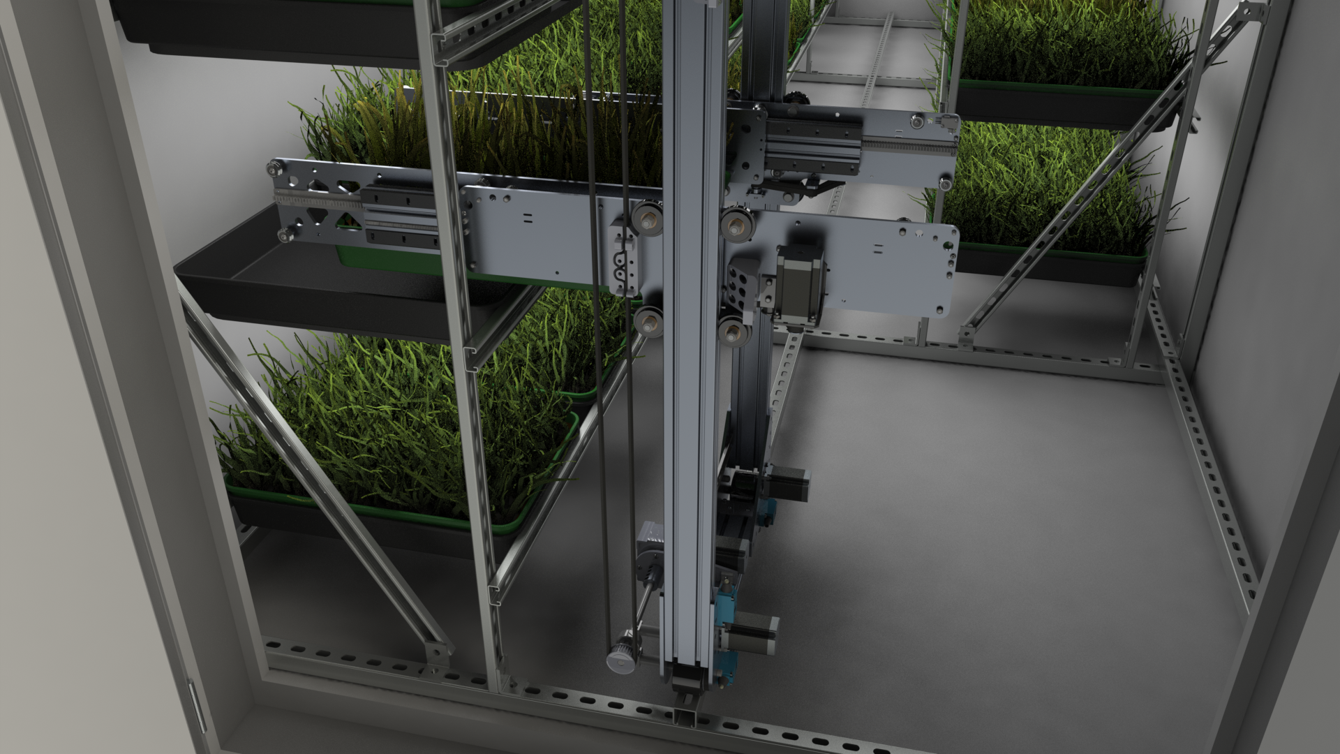
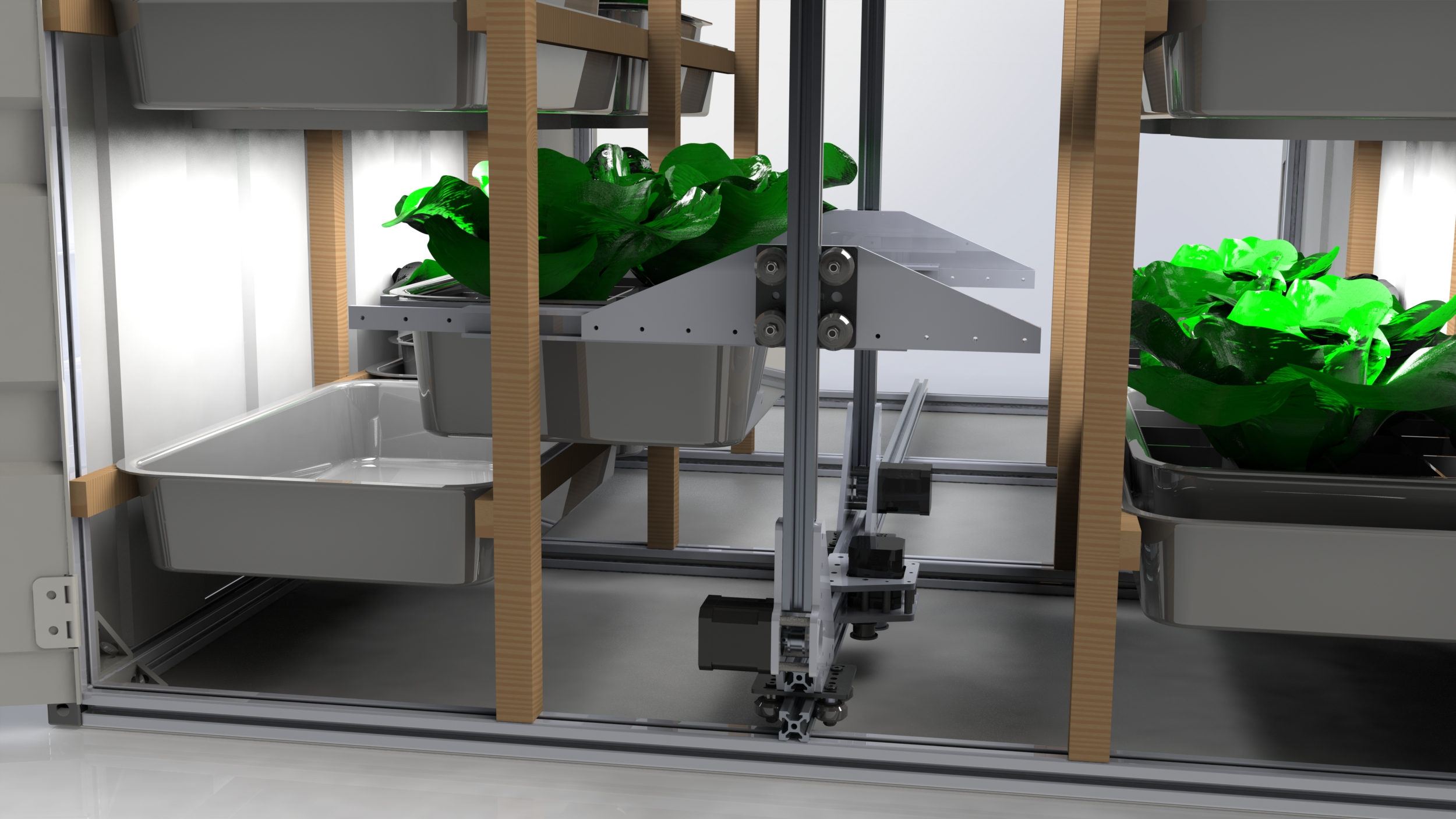
Bi-direction capable full extension drawer slides were not affordable at this scale so OpenBuilds OpenRail linear slides were used instead along with custom waterjet aluminum plate
Gantry long axis simply uses skateboard wheels to ride along unistrut beam with OpenBuilds wheels for lateral alignment
Z-axis uses single worm drive for non-backdriveability and to enable lifting 50+ pound trays with a low-cost motor
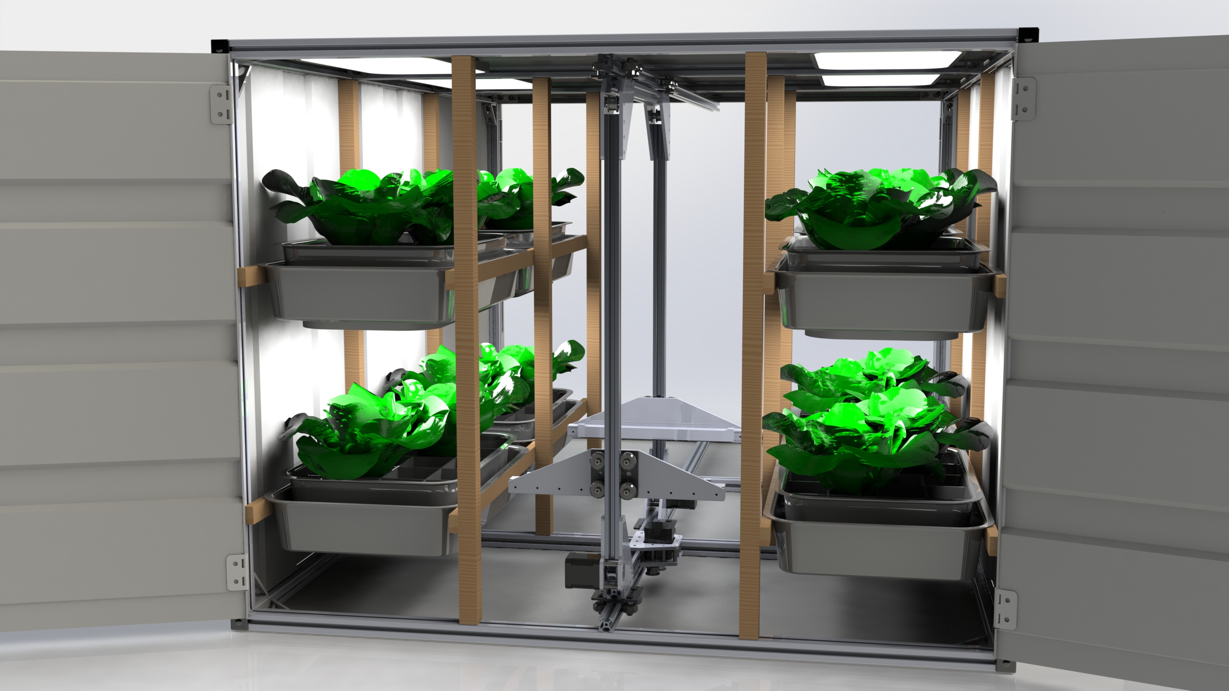
Full Scale Growbox Gantry
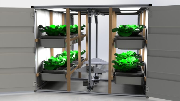
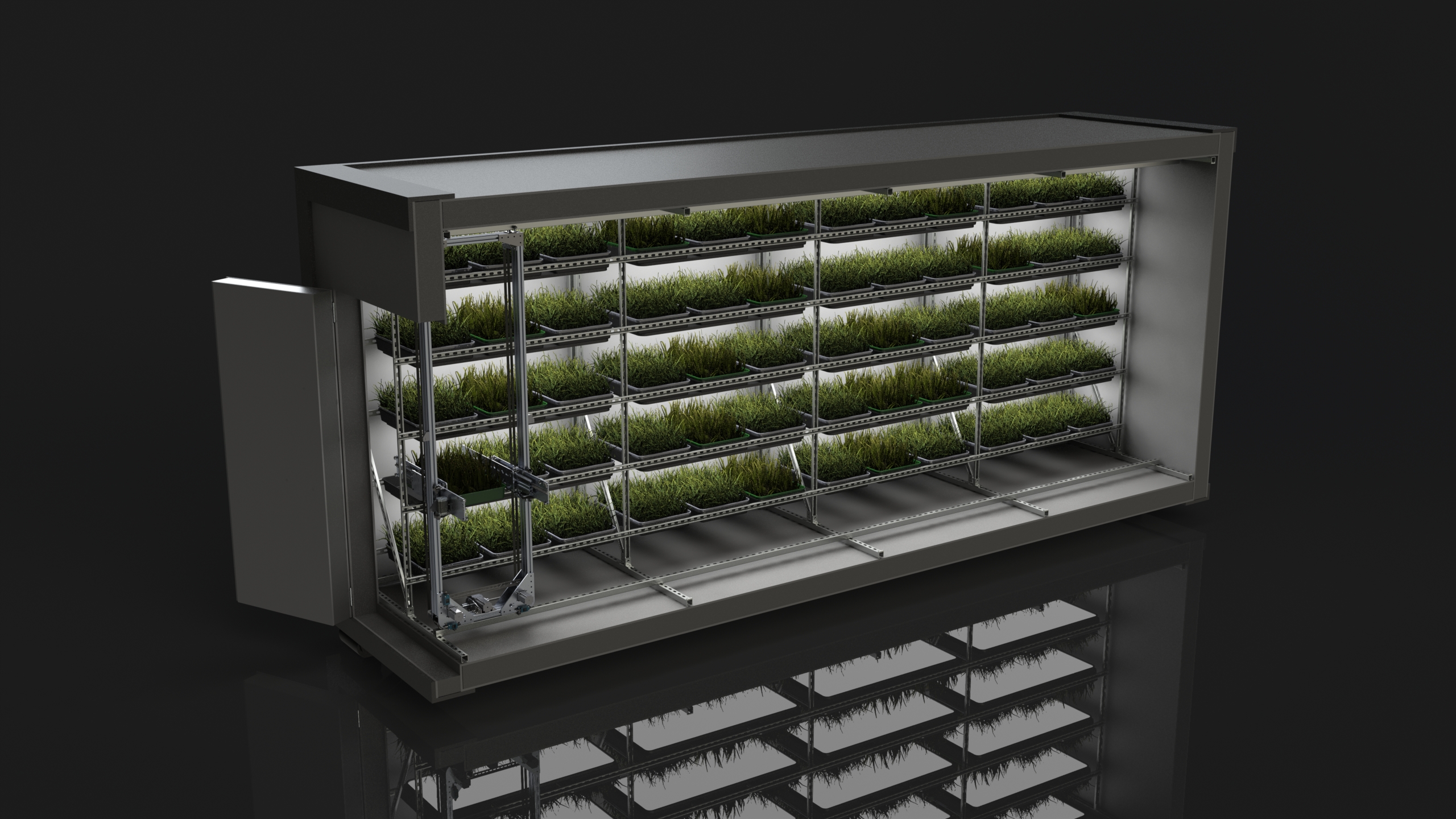
Growbox Cutaway Render
Cutaway render shows envisioned layout
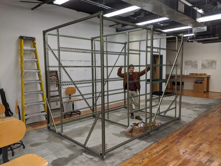
Strut channel structure built at half-length (Marc for scale)
Strut Channel Structure
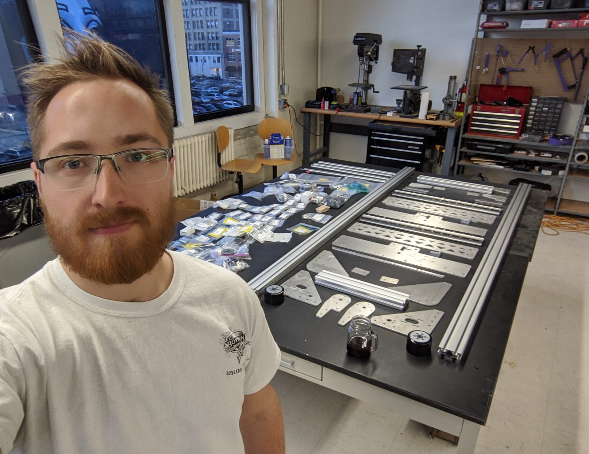
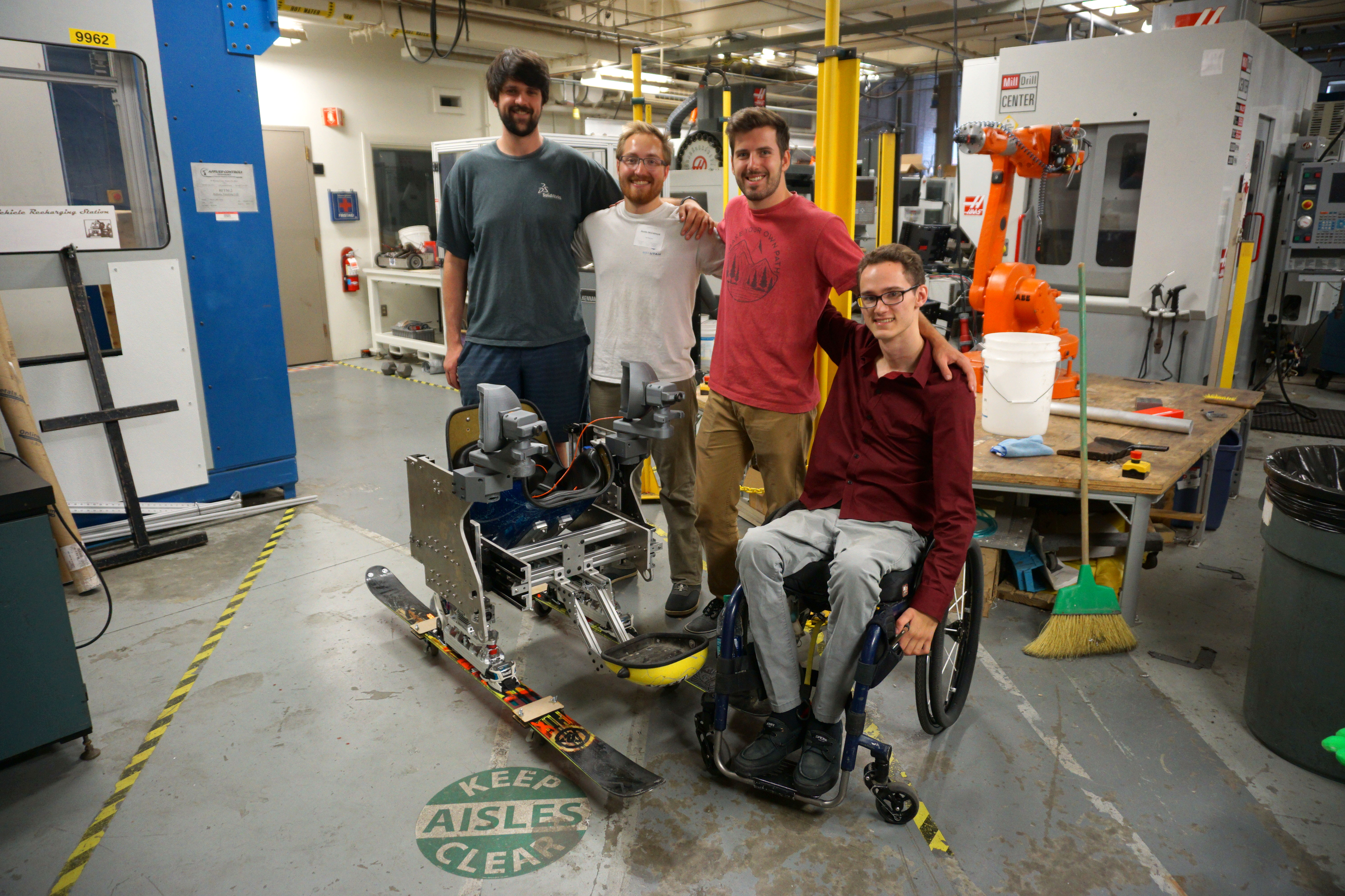
Gantry Parts
An excited Austin with all gantry parts ready for assembly
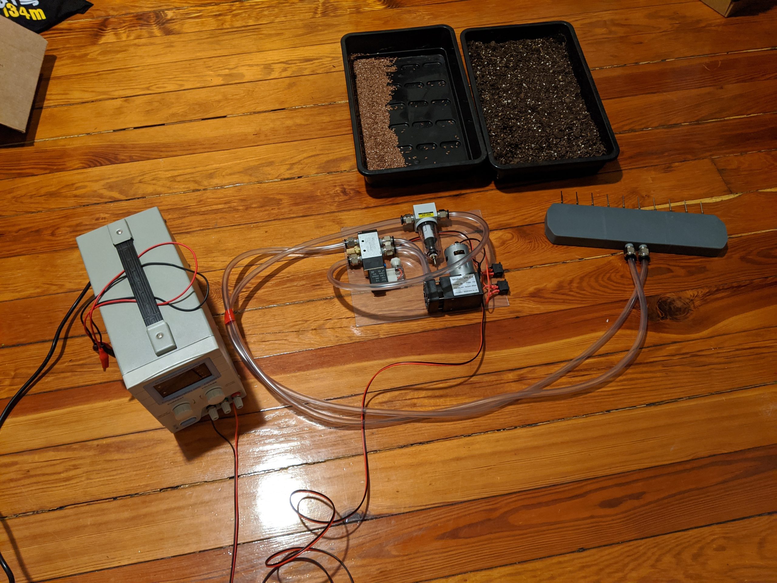
Began prototyping an automated seed planting module
Limited time to work on the project after starting at Formlabs, and the Growbox team eventually changed scope, starting Farmblox
Prototype Automated Seed Planting System
2019
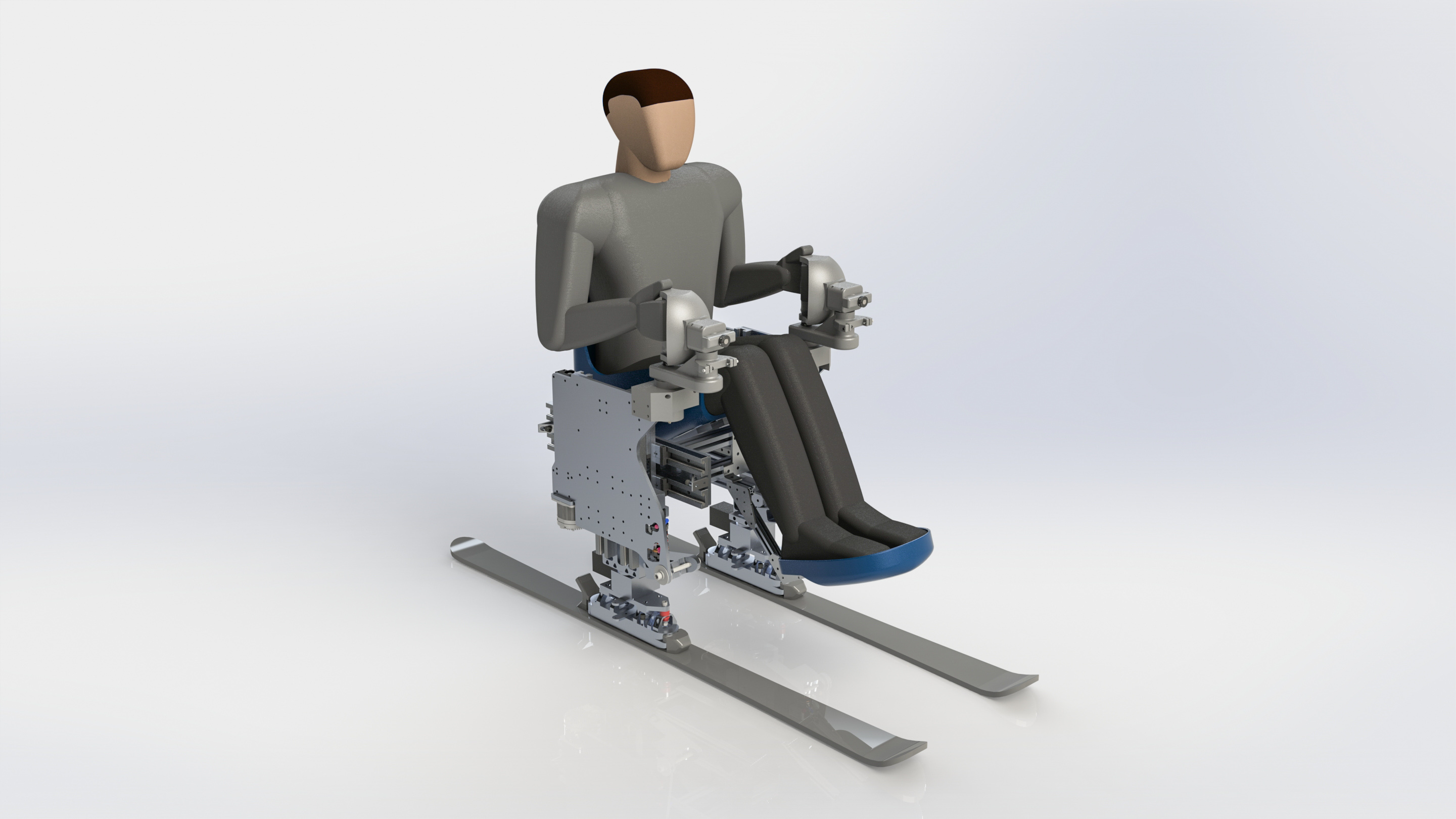
Sit-Ski By Axiomatic Design
Pre-existing State-of-the-Art Sit-Skis
For WPI’s MQP (senior project), I worked with three other team members to redesign a sit-ski from the ground up using the rigorous design theory of Axiomatic Design
State of the art technology has stagnated, and still fails to intuitively mimic non-disabled skiing technique
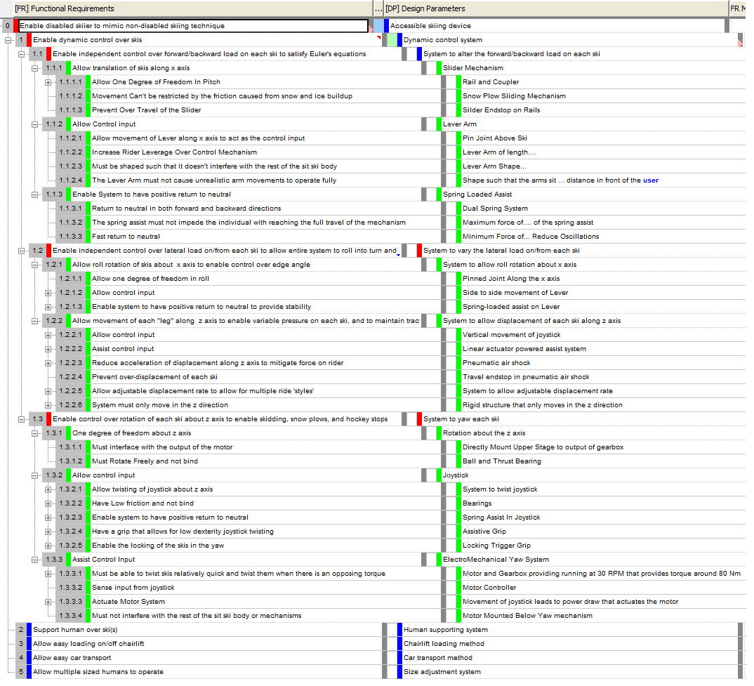
Used Acclaro DFSS software to visually map and break down customer needs (CNs) into functional requirements (FRs) and finally into individual design parameters (DPs)
Independence of components is maximized and complexity is minimized to mitigate unintended outcomes
Started from a blank slate and designed each component to directly satisfy the required functions
Partial Axiomatic FR-DP Decomposition
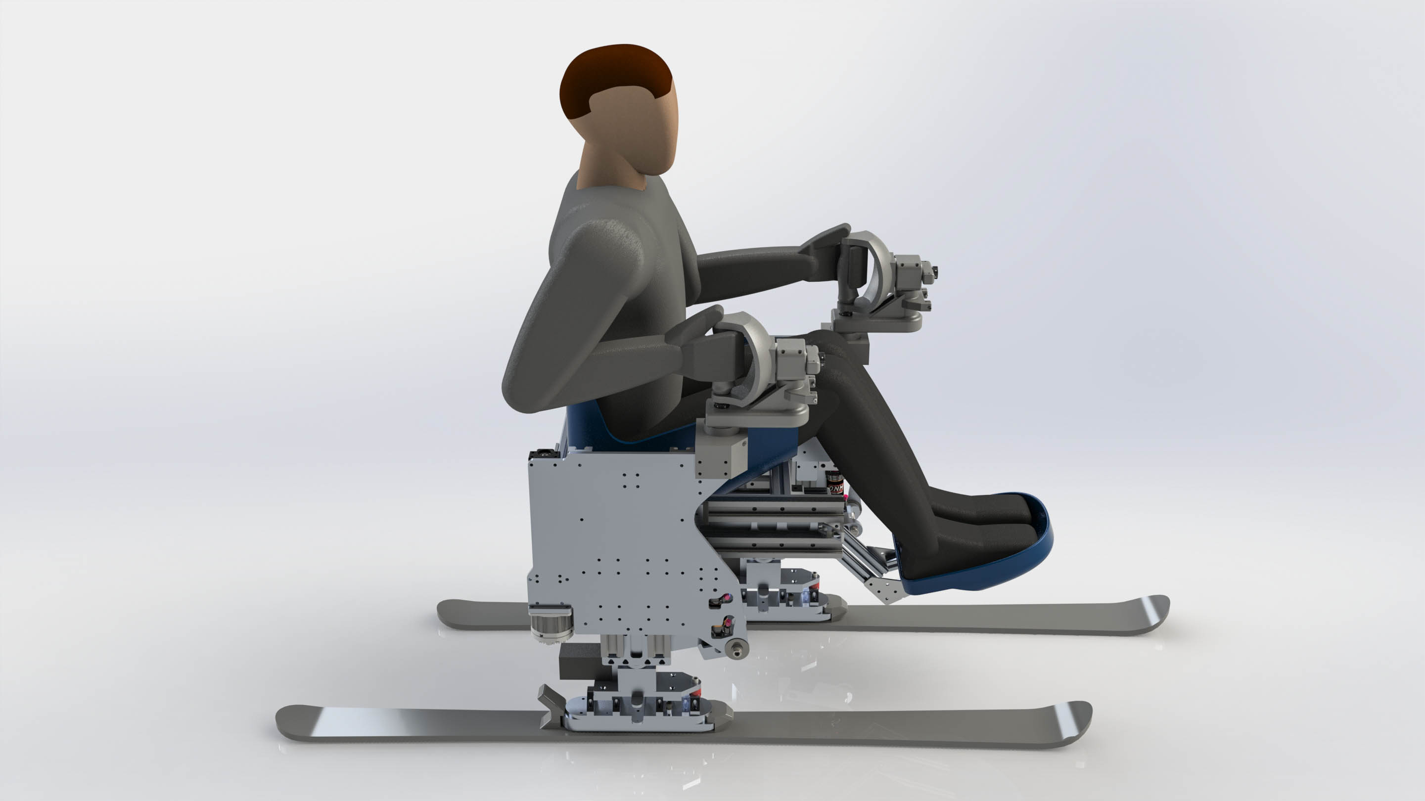
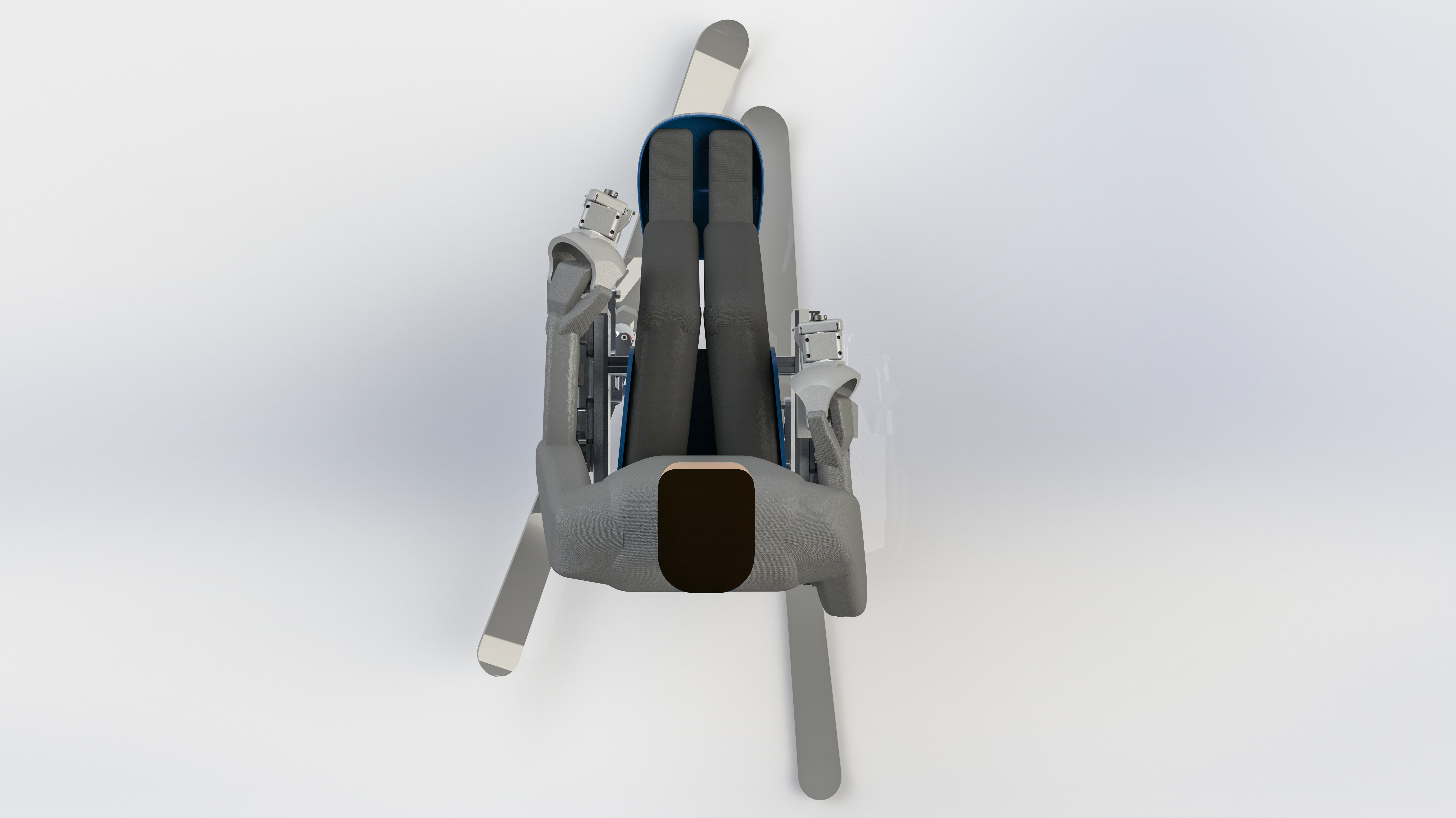
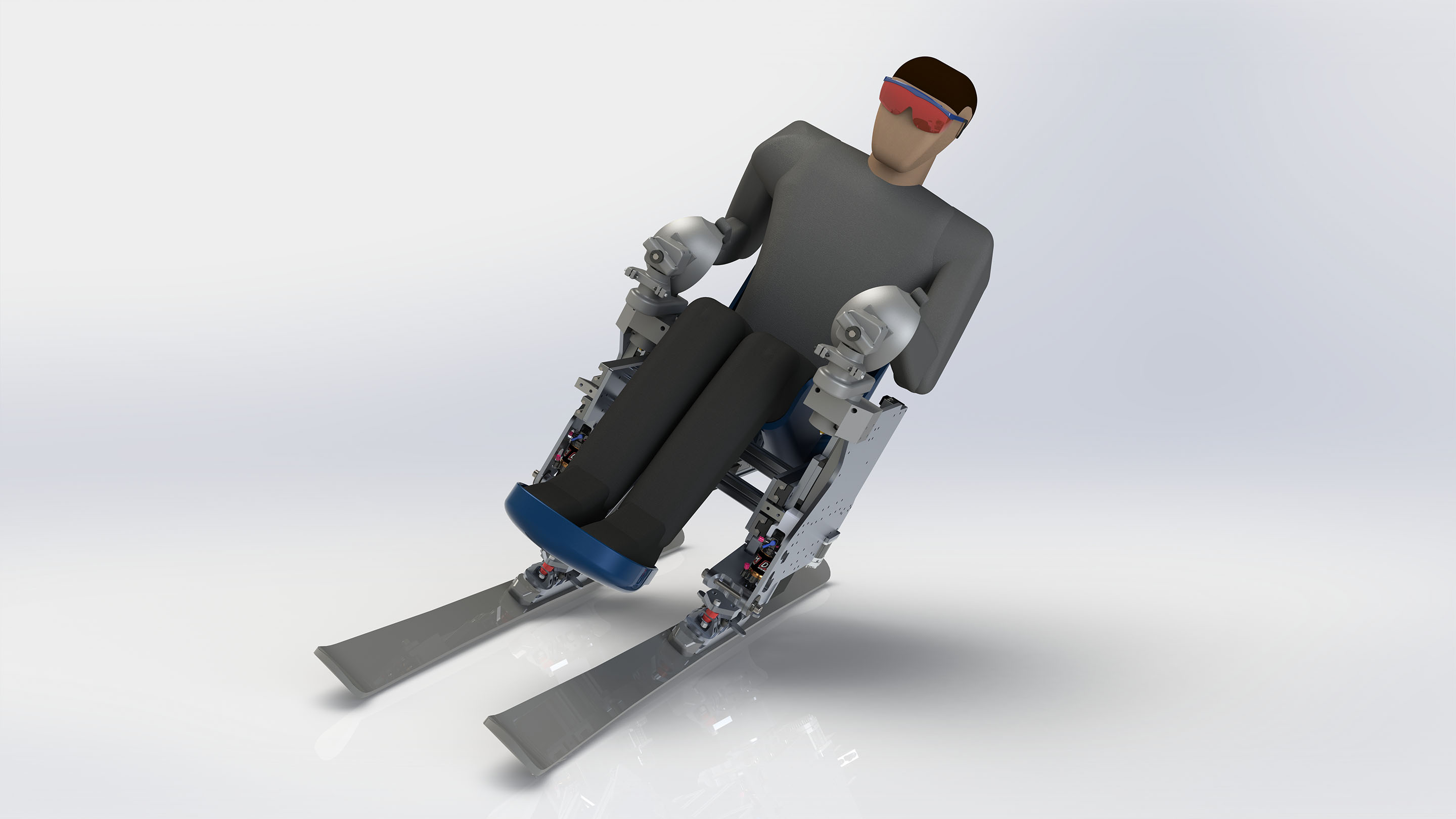
Axiomatic Sit-Ski Render
After many iterations of axiomatic decomposition and revision, a CAD model was created and iterated a few times
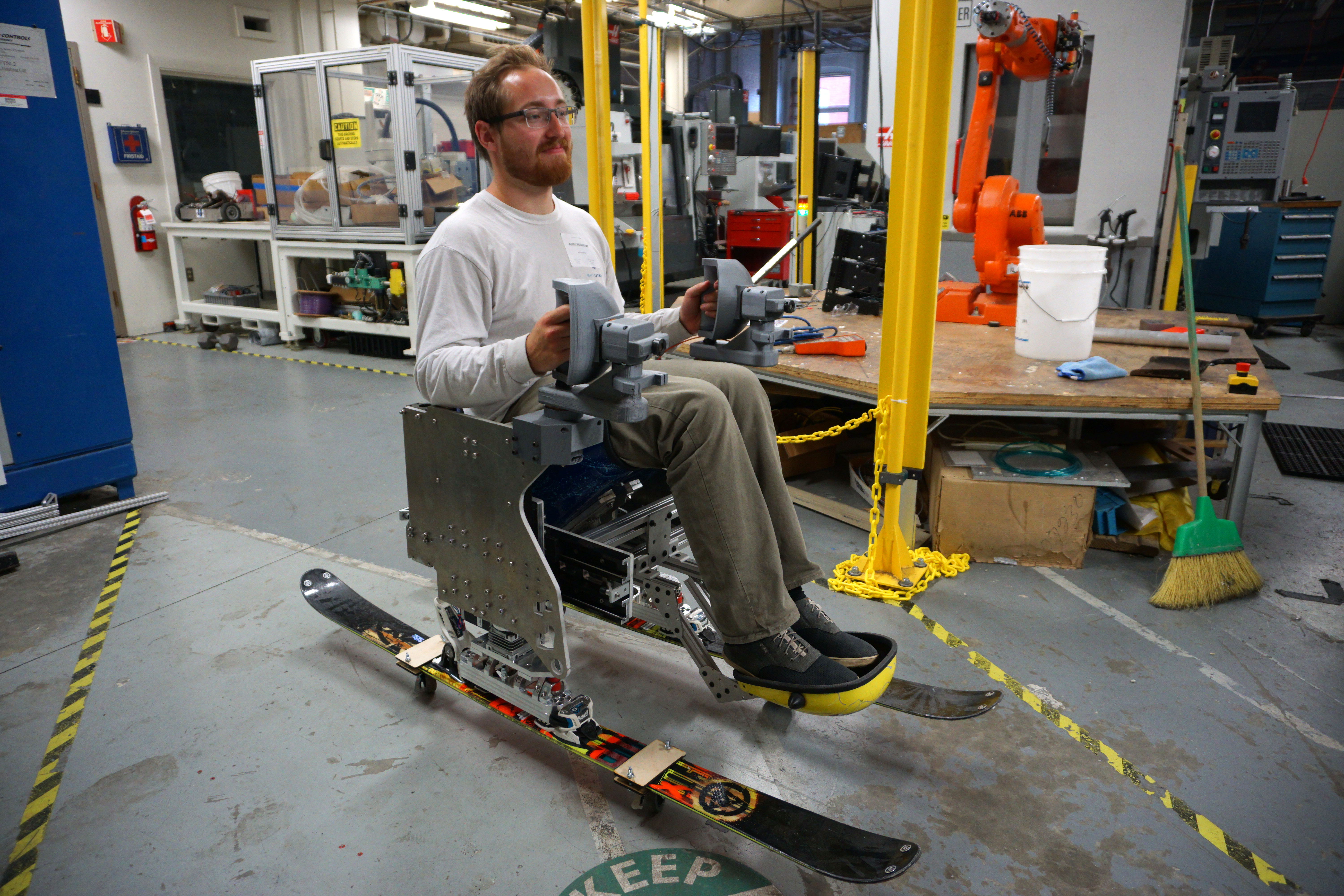
The resulting concept uses a combination of linear slides and pin joints to enable four independently controllable axes on each ski, allowing the user to perform better skiing technique
State of the art sit skis are entirely controlled by shifting the user’s center of gravity despite being strapped into the seat, and demand great abdominal strength that paraplegic athletes may not have
One of the most important and often overlooked requirements for completing a carved ski turn is control over fore/aft center of gravity
Fore/Aft CG control
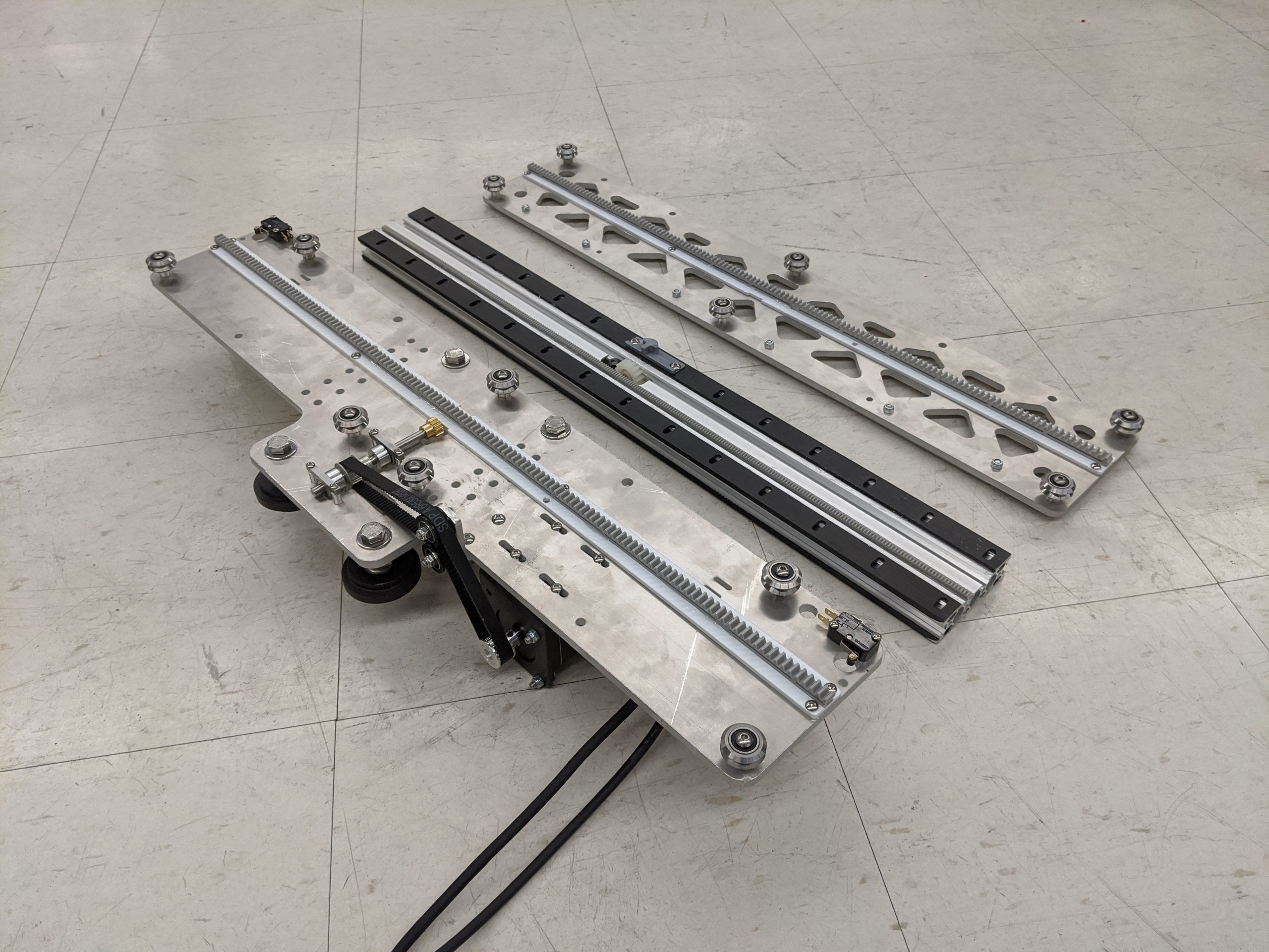
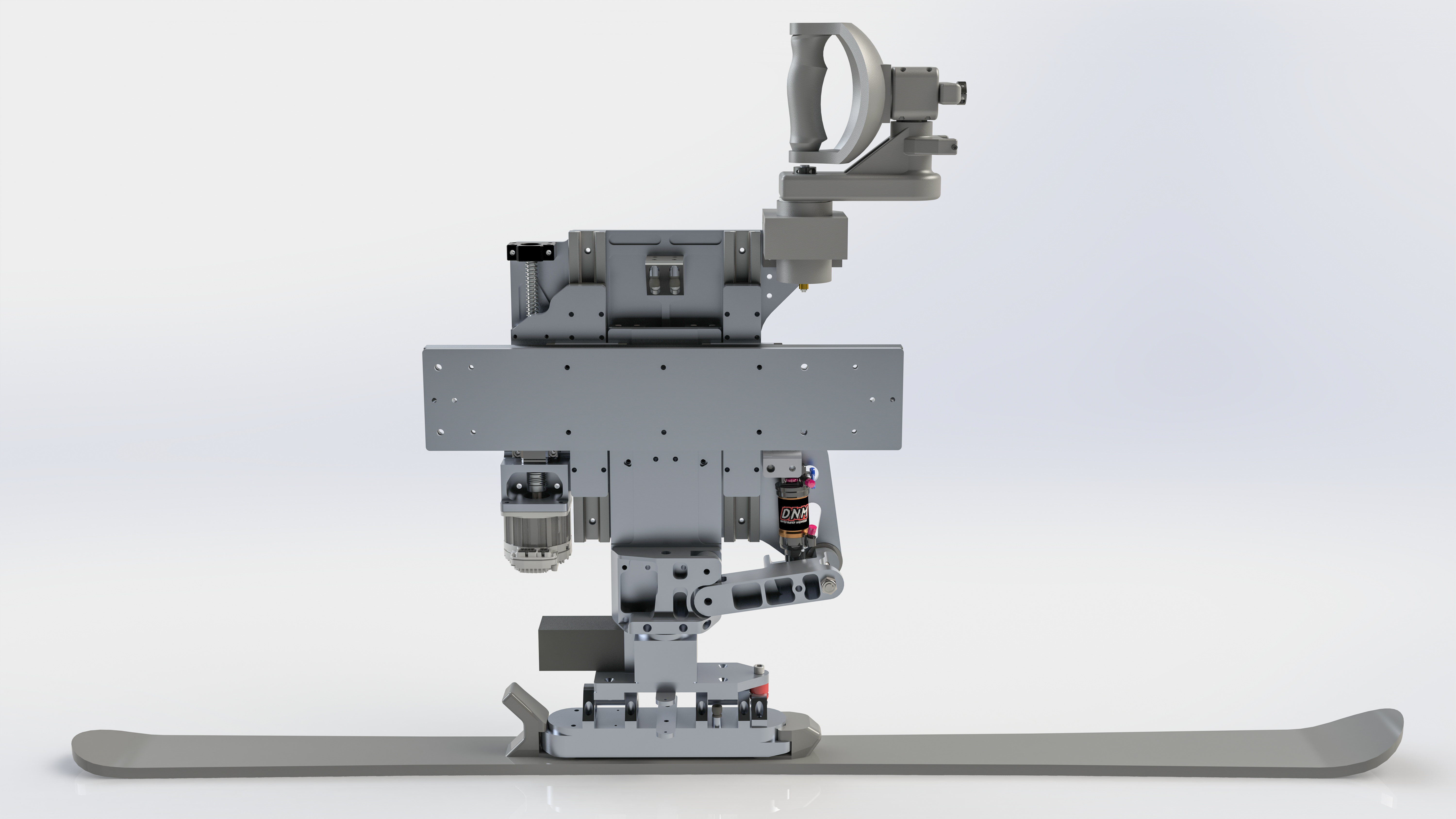
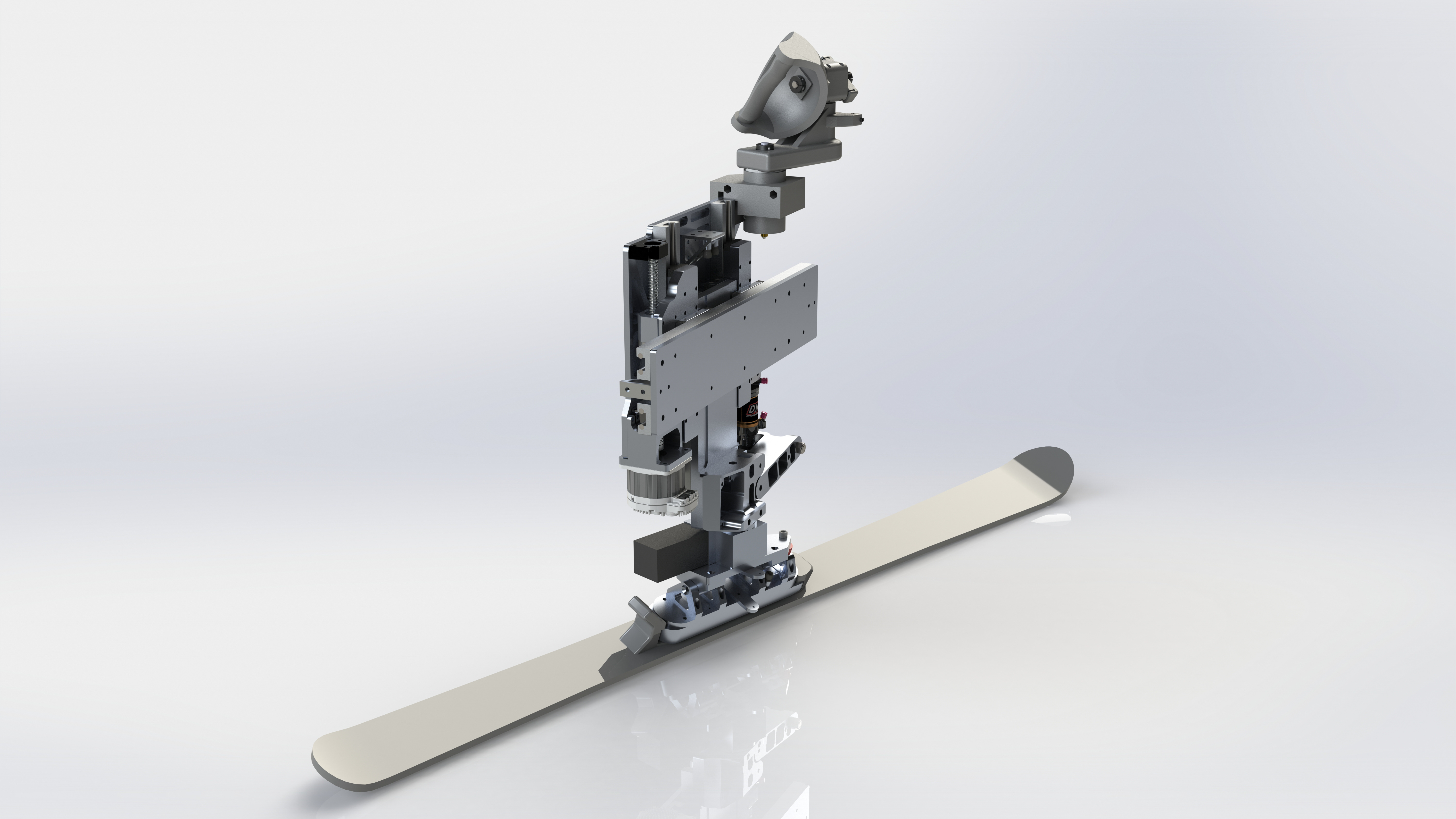
Sit-Ski "Leg"
The controllable axis on each “leg” are: passive fore/aft translation, active assisted vertical translation, active yaw rotation, and passive roll rotation
A nested set of linear slides allow for almost 150 mm of suspension travel, and are damped by a mountain bike air-shock
Frame is made out of T-slot aluminum to simplify manufacturing and allow for adjustability
Four linear roller carriages are used on each linear axis to hold high moment loads, allow for slight misalignment, and allow for moderate environmental conditions yet still have low friction
Fore/Aft CG control
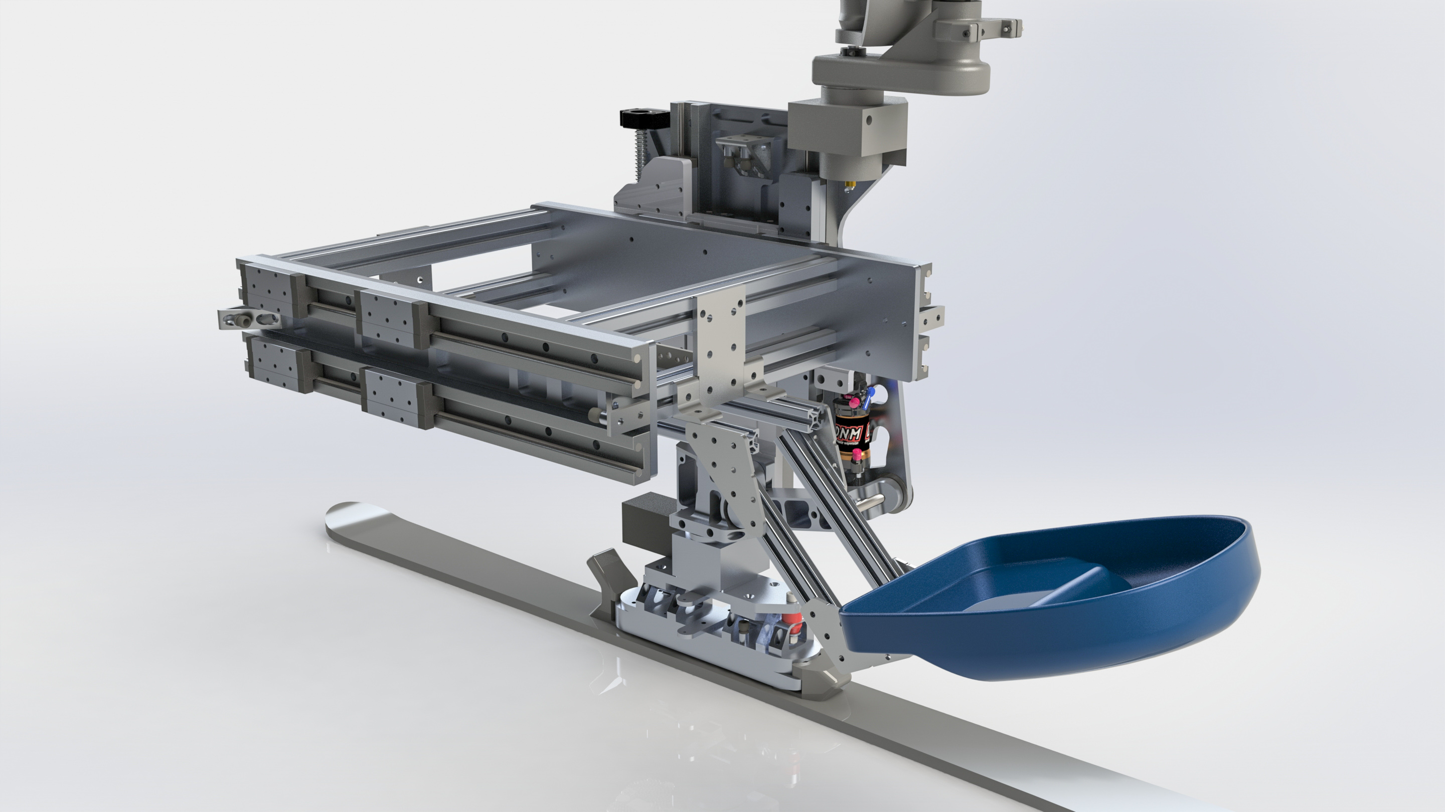
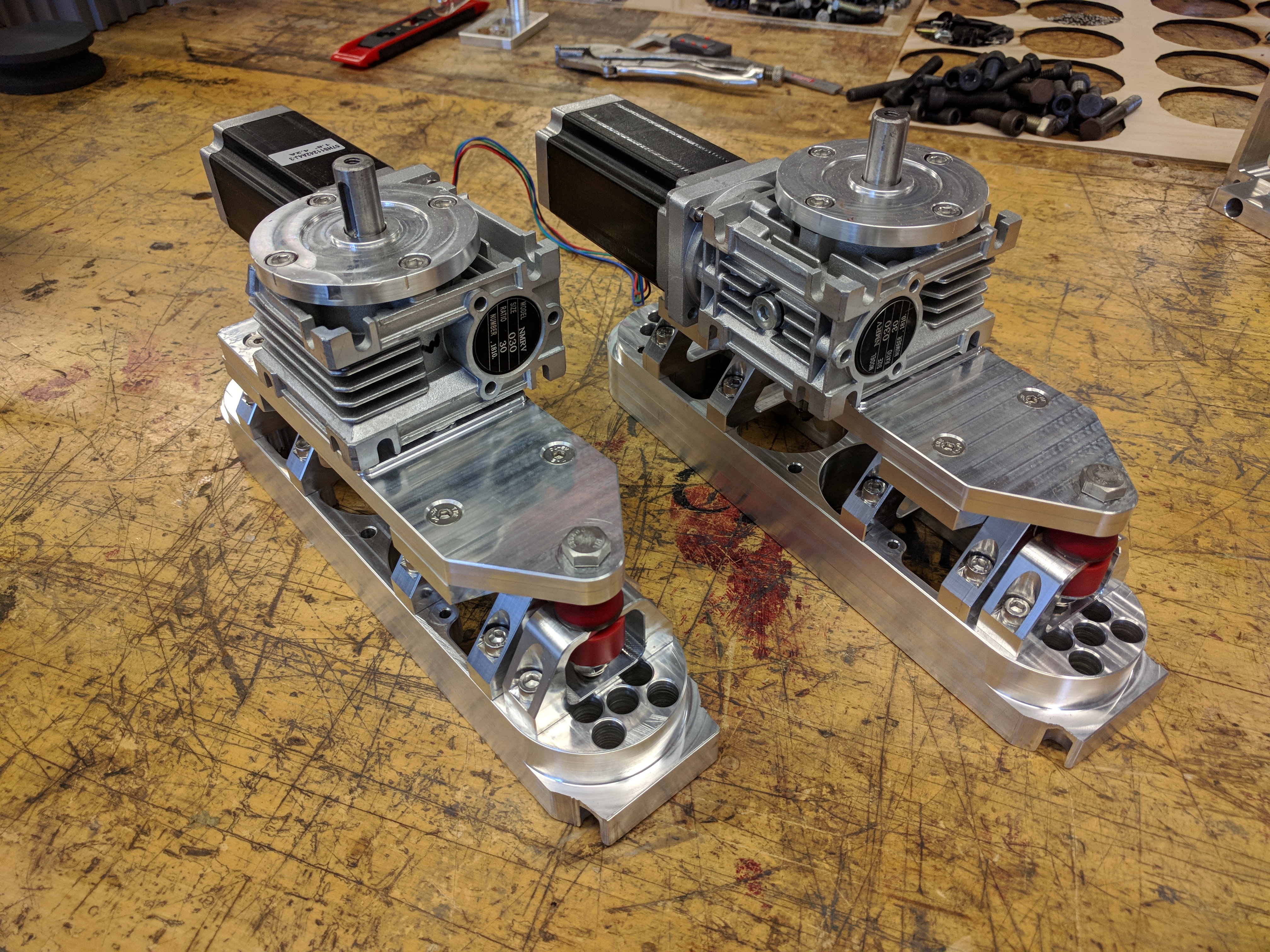
Actuated Sit-Ski "Leg"
Each ski intuitively mimics the position of its correlated joystick
Yaw is controlled by a worm-drive stepper motor to prevent back-driving
Roll is controlled by bowden cables attached to the joystick with a 2:1 mechanical advantage
User is able to perform a snowplow (pizza) turn, making turning and stopping easier for beginners
Snowplow Turn
Carved Turn
With so much added control, the user is also finally able to perform better skiing technique
Large plates were waterjet cut from 6061 aluminum, and all parts were lightweighted with CNC mills
Smaller aluminum parts were entirely CNC milled
I created all toolpaths and performed all CNC operations
Parts Ready to be Assembled
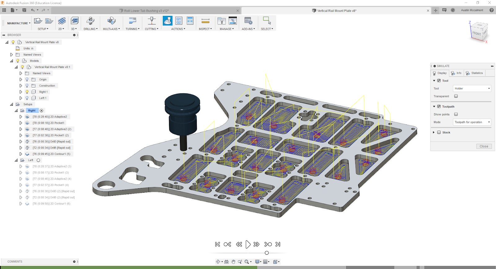
Fusion 360 CAM
Toolpaths were programed using Fusion 360
A simple example of lightweighting on a 3/8 aluminum waterjet plate is shown
Auto-probing and toolpath optimization were performed to reduce cycle times
A video of me lightweighting a linear rail in a Haas VM2 is shown
Three back-to-back setups for a roll axle block are shown running in a Haas Super Mini Mill
Video is warp-stabilized, looks jello-y but better than shaky (should have used a Movi)
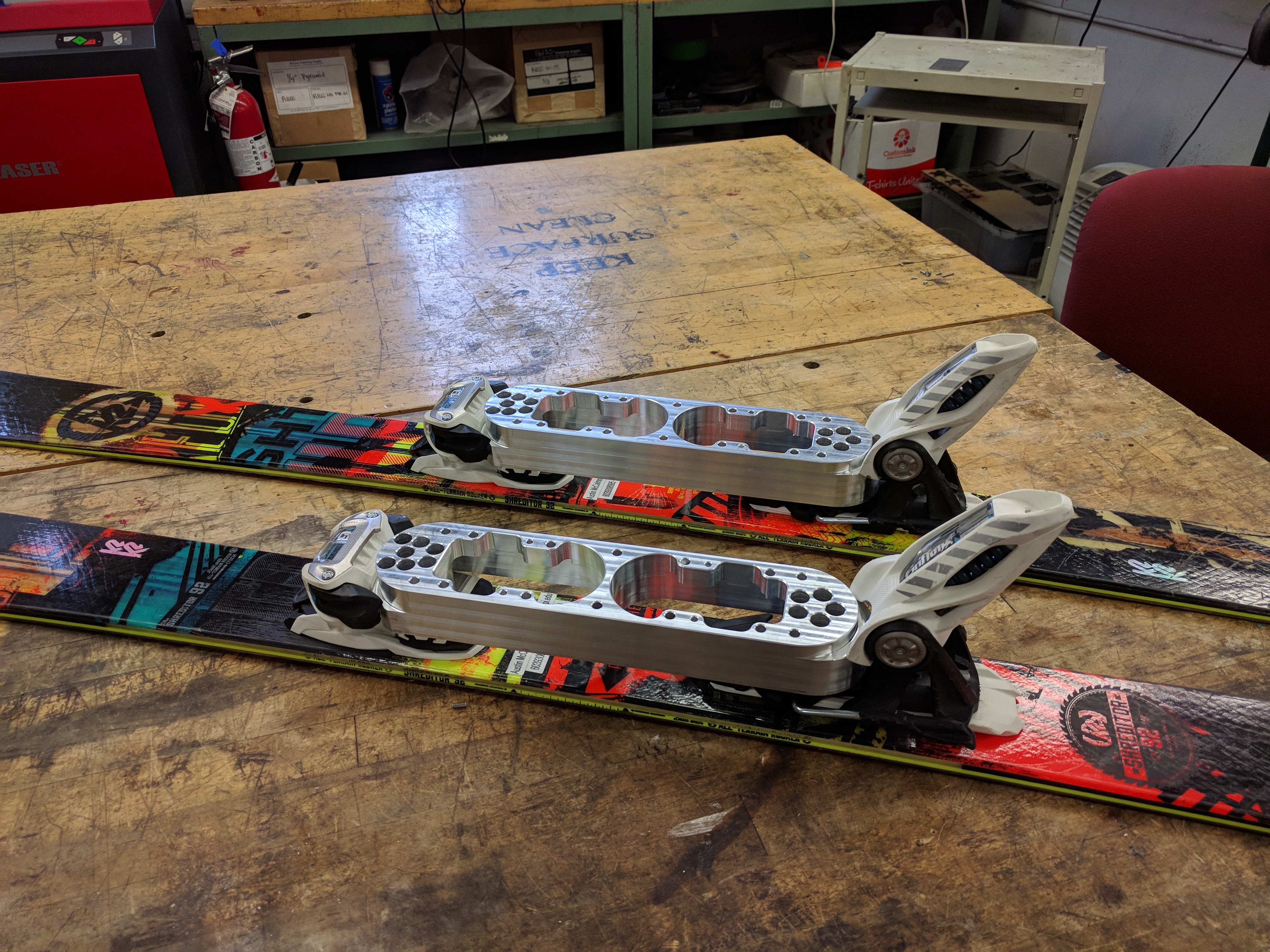
Binding mounts were designed and machined to mimic 330-mm BSL ski boots and clip into my skis
Binding Mounts
Yaw Mounts
Each yaw mount required six setups
The assembled “ankles” are shown
Sit Ski "Ankles"
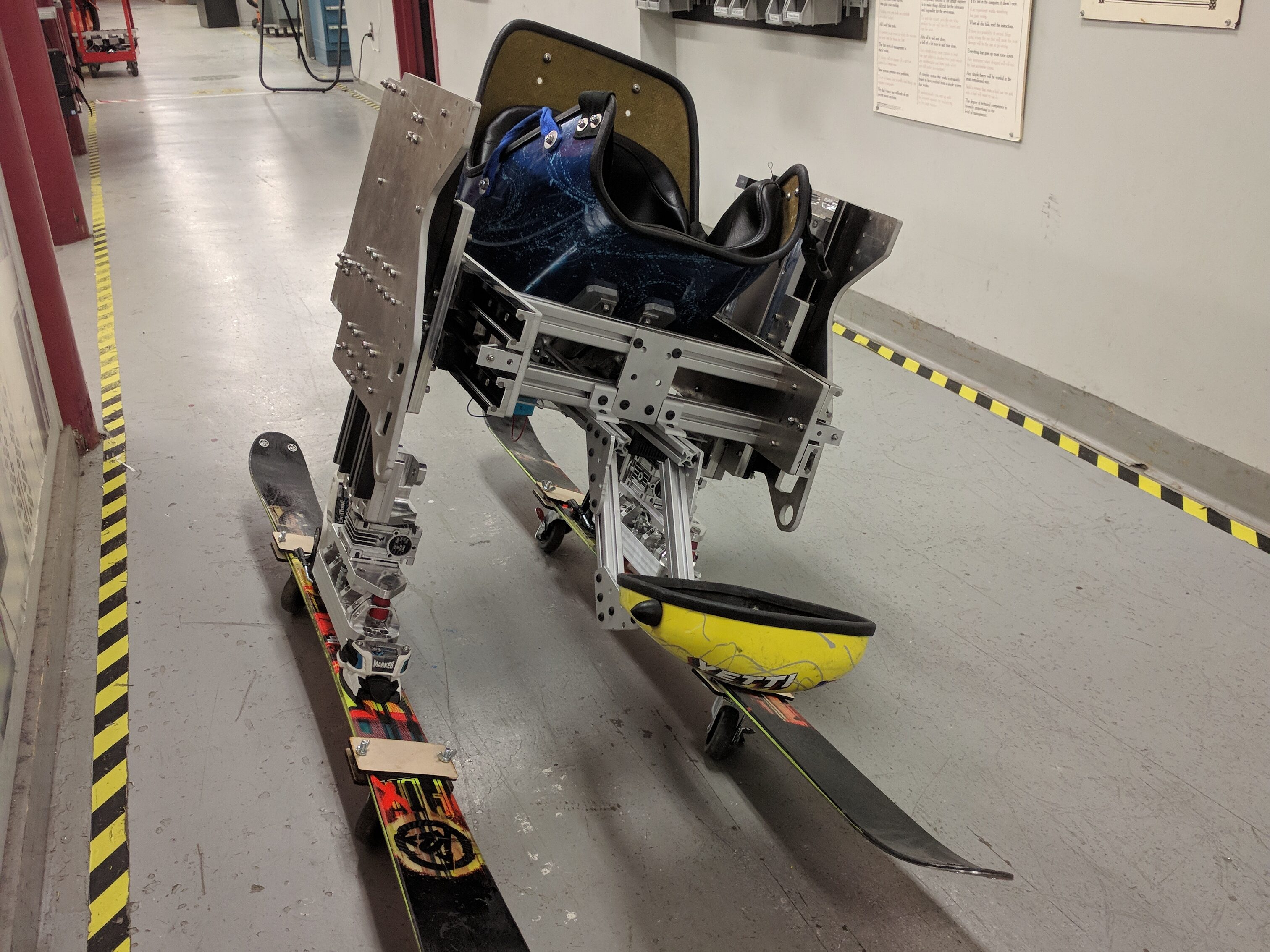
Sit Ski Leaning to One Side
Assembled sit ski without joysticks is shown leaning to one side
The sit ski was assembled with 3D printed joysticks
Me Sitting in the Device
MQP Team With Sit Ski
The team consisted of David Parker, myself, Jeff St. Hilaire, and Jared Grier
Our advisor was Christopher Brown
Our poster for WPI’s MQP presentation day is shown
Worked with a team of WPI students in a potential startup effort to create an automated hydroponic system
The concept was designed to work in a shipping container to be self-contained and portable
Use of shipping containers for hydroponics has been explored by others however none are fully automated
Render of 1/3 scale prototype shown
Making the system automated has the potential to reduce plant/vegetable costs to be competitive with supermarket prices, while maintaining local grown quality, year round
Hydroponics allow plants to get more consistent nutrients and light, making them grow faster
AI planned to further optimize plant growth
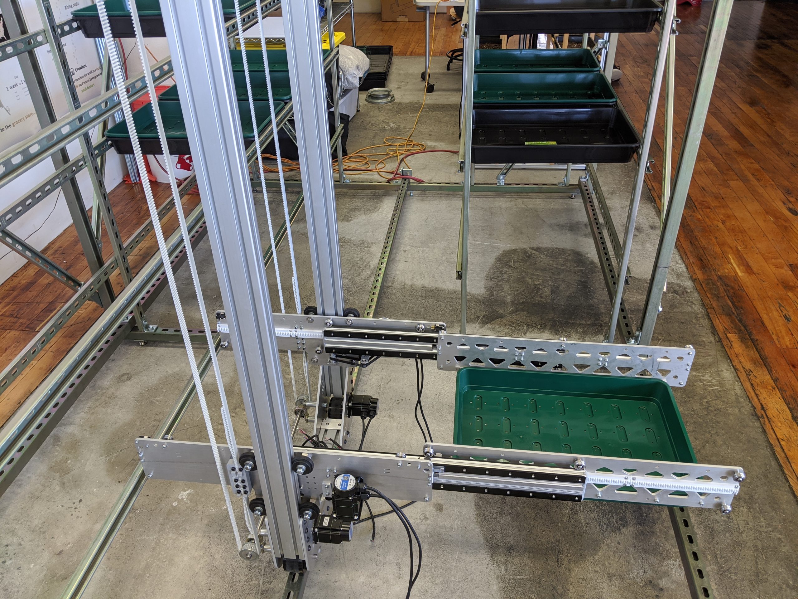
Plant Shelves With Central Gantry System
Gantry Moving a Plant Tray
I was the hardware engineering lead for the team and designed all concepts shown
A stepper-driven, bi-directional, full-extension telescoping end-effector was designed to maximize growing area
The gantry system is able to move plant trays from a seeding module, to grow stations, and finally a harvesting module without human intervention
Entered multiple entrepreneurship competitions and won initial funding and lab space at Worcester Clean Tech Incubator
Prototype Hardware at WCTI
Electrical Wiring on Gantry
Hardware is designed to scale up to a full-size concept
V-slot roller carriages allow for almost unlimited linear travel at a low cost
All electronics except power supply are contained within gantry
Prototype bi-directional slides driven by fixed stepper motors
Used drawer slides to save on prototyping costs
Actuated Bi-Directional End-Effector
Gantry could successfully place and retrieve plant trays
Next steps were to add hydroponic plumbing and lighting, then design seeding and harvesting modules
Mentorship recommended building a full scale prototype to attract more serious investment. See Automated Hydroponics Full Scale, above
2018
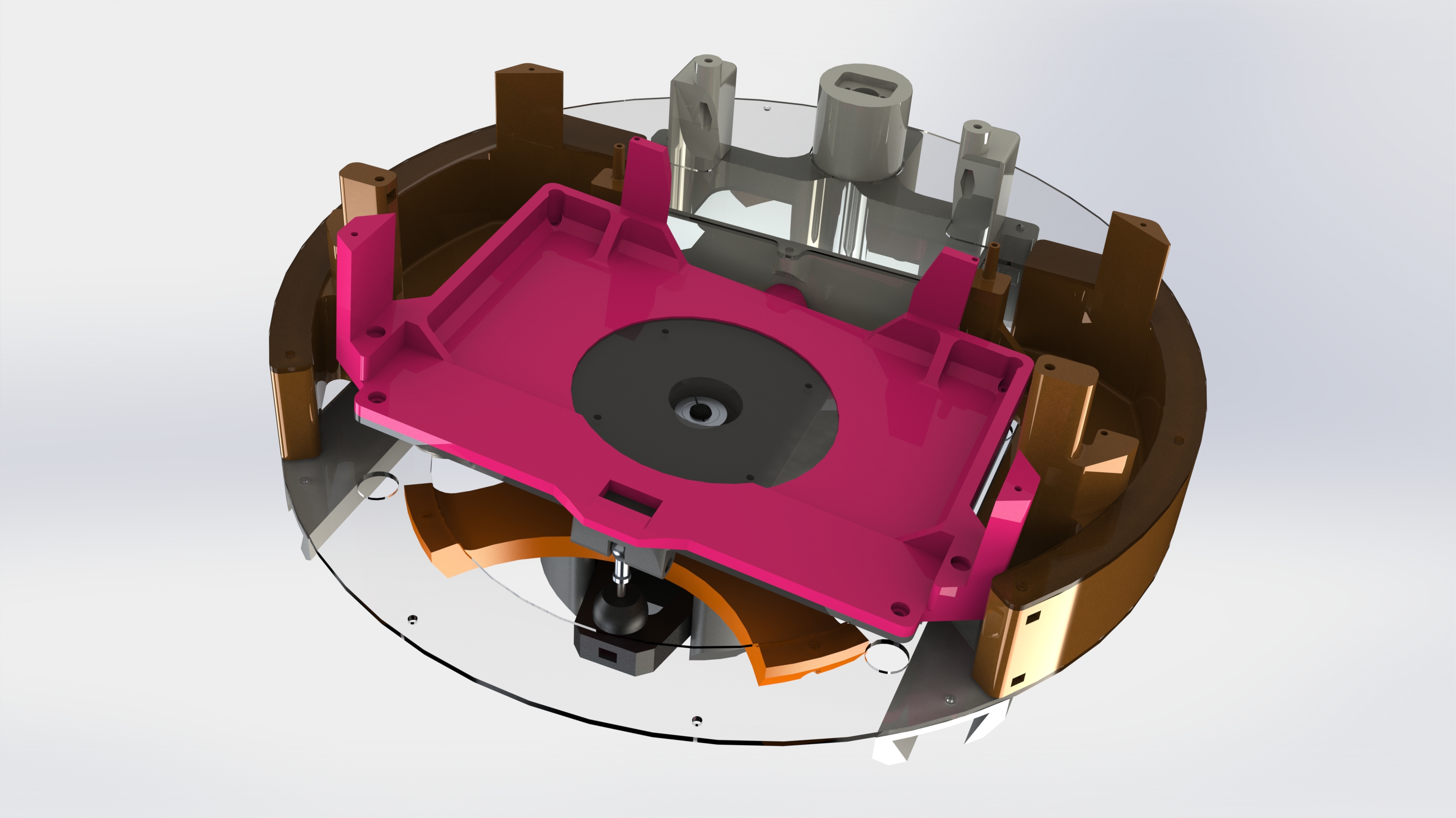
Roomba Test Platform
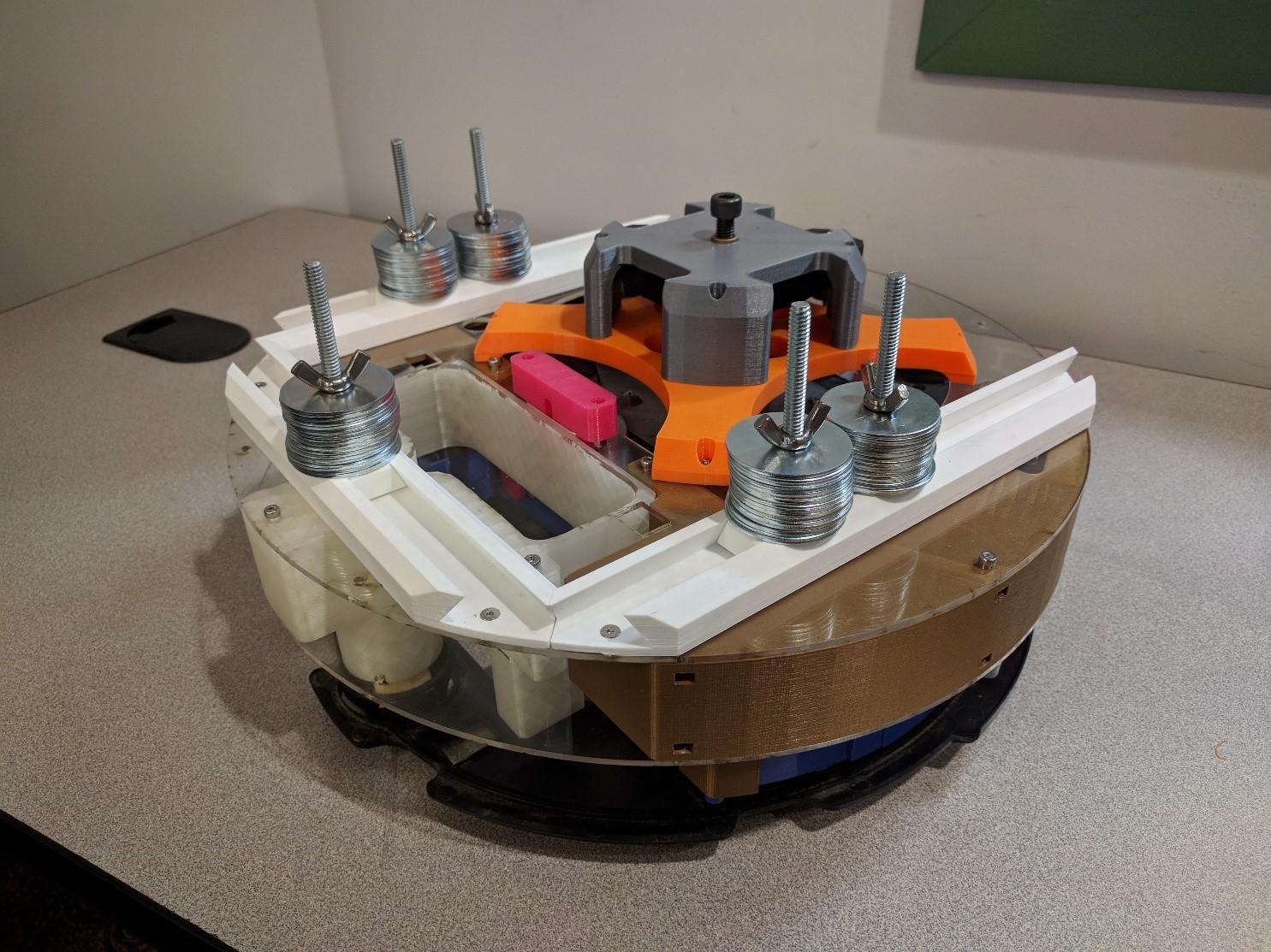
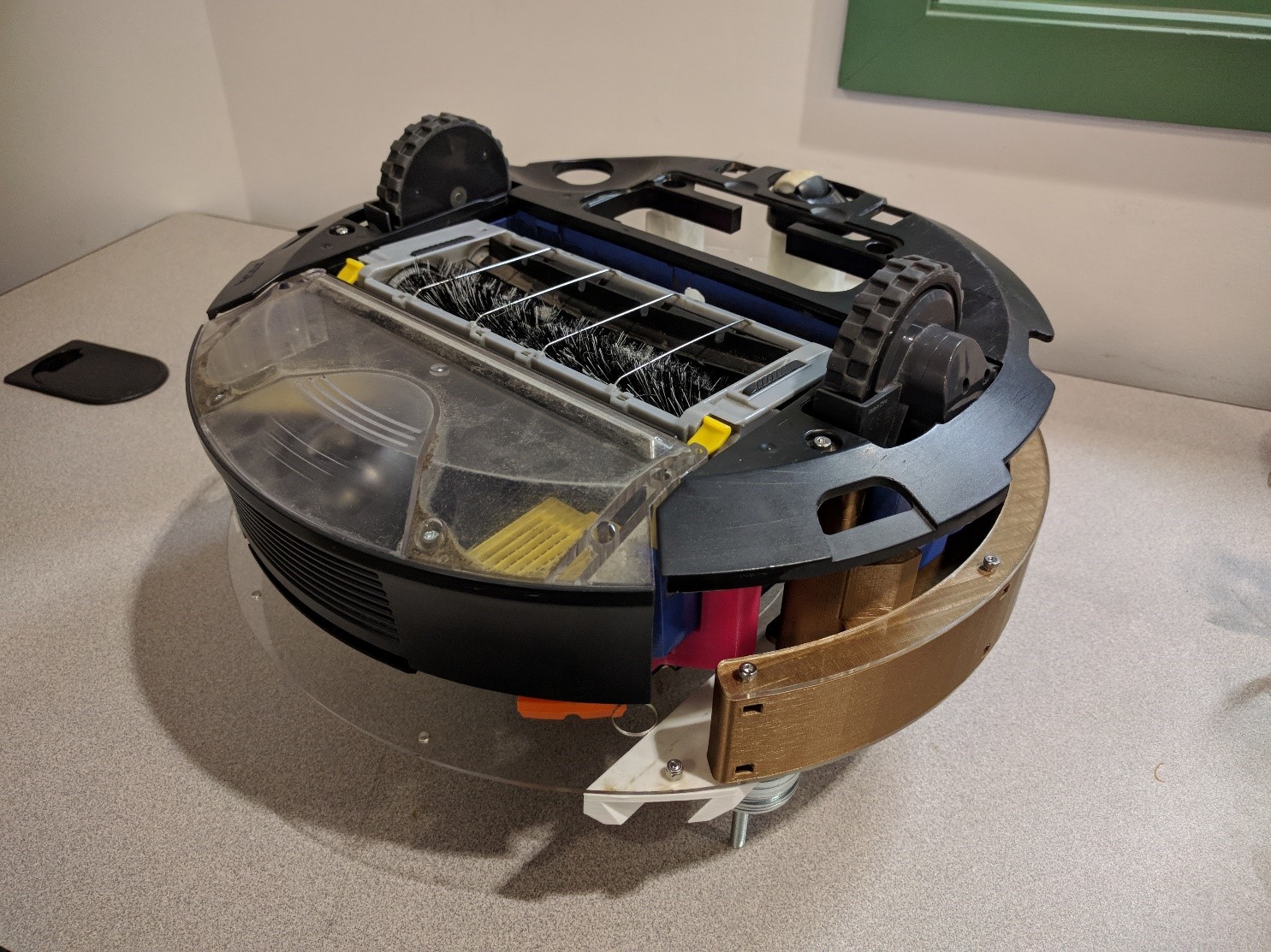
Top Render of Roomba Test Platform
Advanced Design class gave the task of designing a cleaning module test platform for iRobot (rendered colors based on final 3D printed part colors)
Cleaning module mounting plate required to be adjustable by 5 degrees in pitch and roll, and adjustable in height by 10 mm with a resolution of 0.2 mm
Bottom of Test Platform
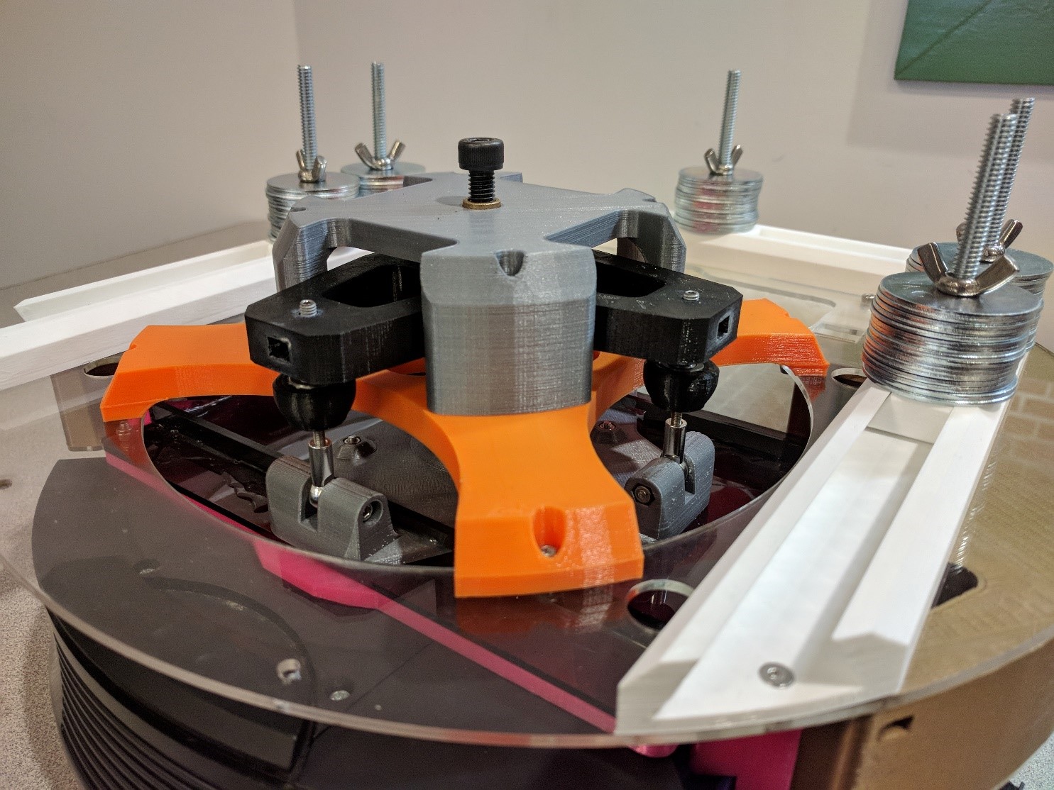
Angled Mounting Plate
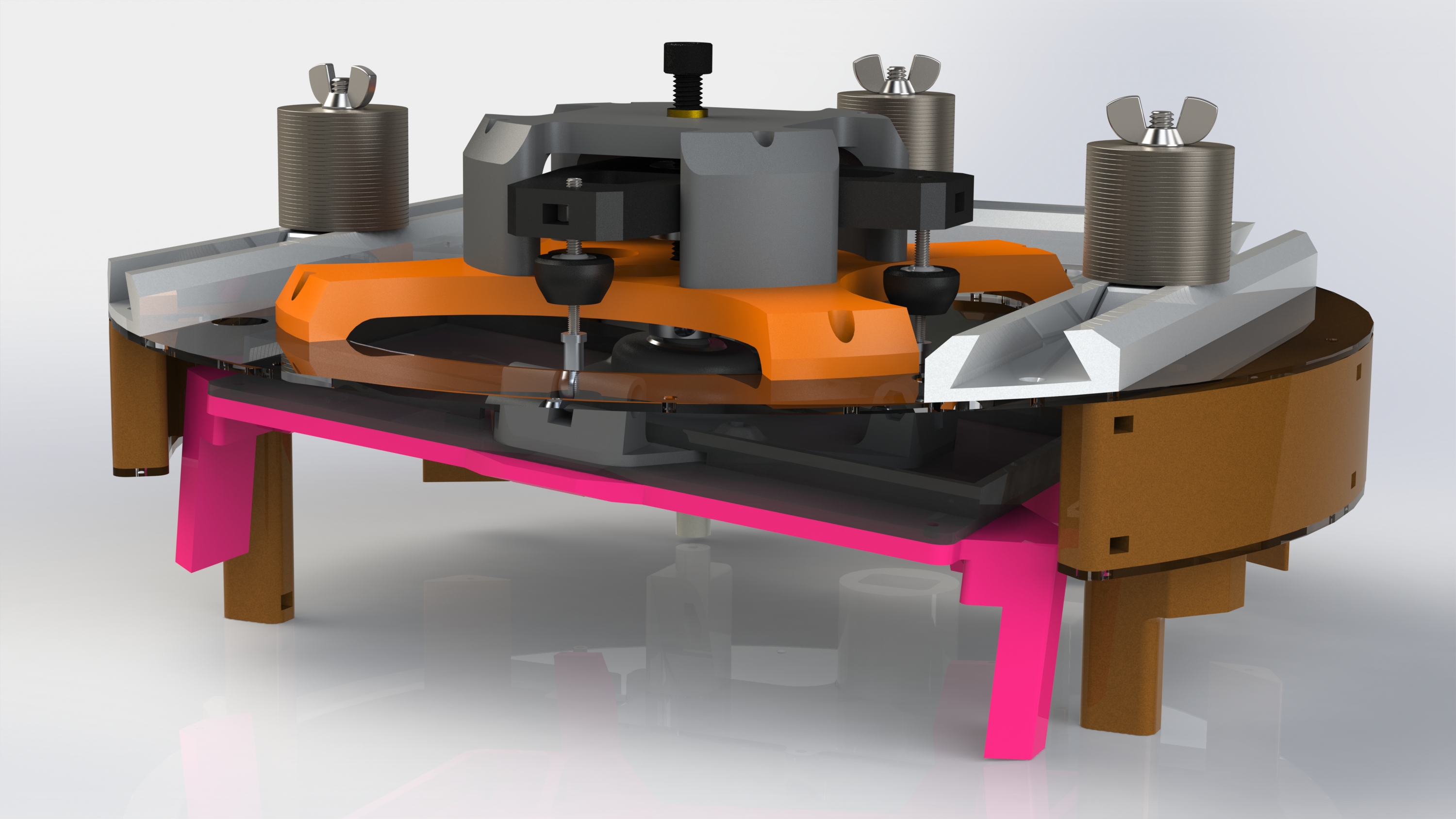
Height controlled by topmost black screw and angle controlled by two silver set screws on ends of black arms
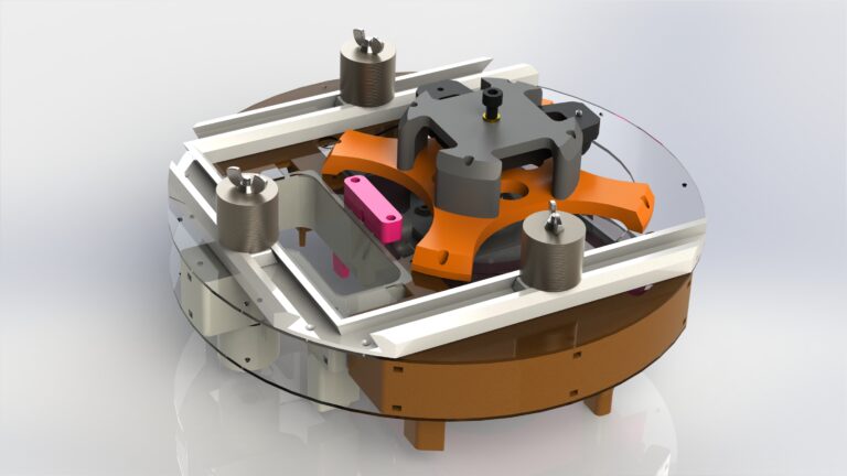
CoG and total mass adjustable by sliding stacks of washers
De-coupled height and angle adjustment mechanism inspired by a helicopter swashplate
Central ball joint allows angulation, horizontal pin in vertical slot on left prevents yaw rotation
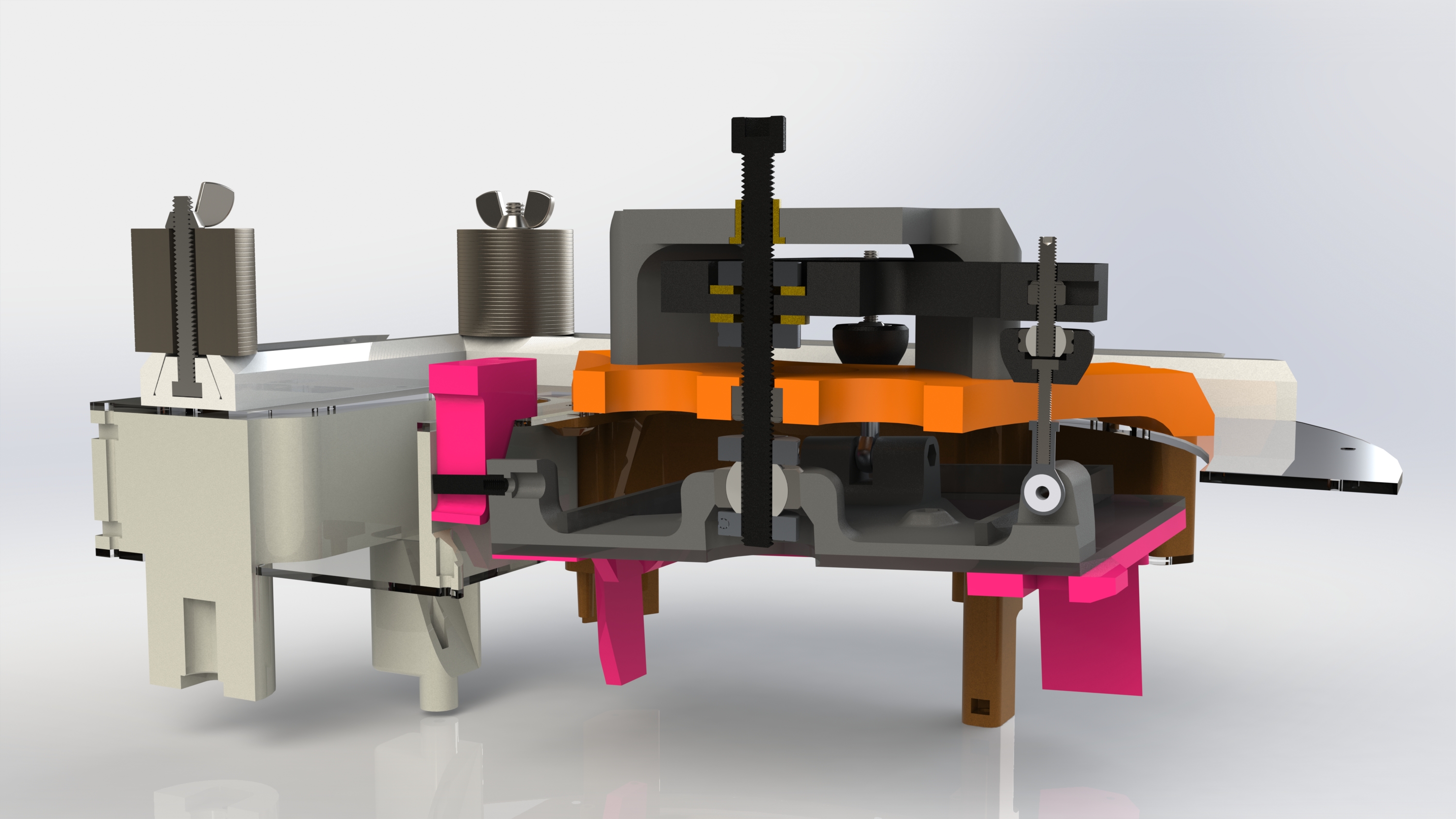
Cross Section of Test Platform
Animation of Height Adjustment
Height adjustment is the first moving stage from the grounded frame
Green M8 set screw “shaft” threads through red lock nut
Upper bushing adds second support to rigidly keep shaft vertical
Shaft collars clamp upper yellow arm perpendicular to shaft and keep lower ball joint in place
Cross Section of Height Adjustment
Animation of Angle Adjustment
Pitch and roll adjustments make up the second stage of movement
M4 set screws thread through lock nuts in upper yellow arm
Lower linkage rod ends are aligned with axes of rotation to prevent binding
Green standoff on left prevents blue plate from yawing (anti-rotation bracket)
Cross Section of Angle Adjustment
Manufactured Test Platform
Designed and built in roughly 5 weeks. Test platform uses stock Roomba motors and wheels, and allows for mounting of battery and bottom skin
Height adjustment screw constrained by locknut in orange part
Angle adjustment screws constrained by locknuts in black “L” shaped part
Angle adjustment linkages properly constrained by rod-ends and inline ball joints
Manufactured Adjustment Mechanism
Roomba Hardware Attached to Test Platform
Height and angle adjustment tested to well within specified tolerances using a dial indicator
Final product exceeded customer expectations
Wearable Biometric Sensor
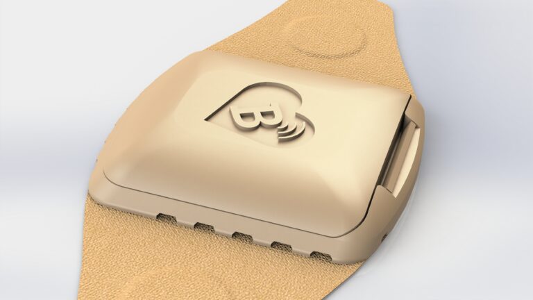
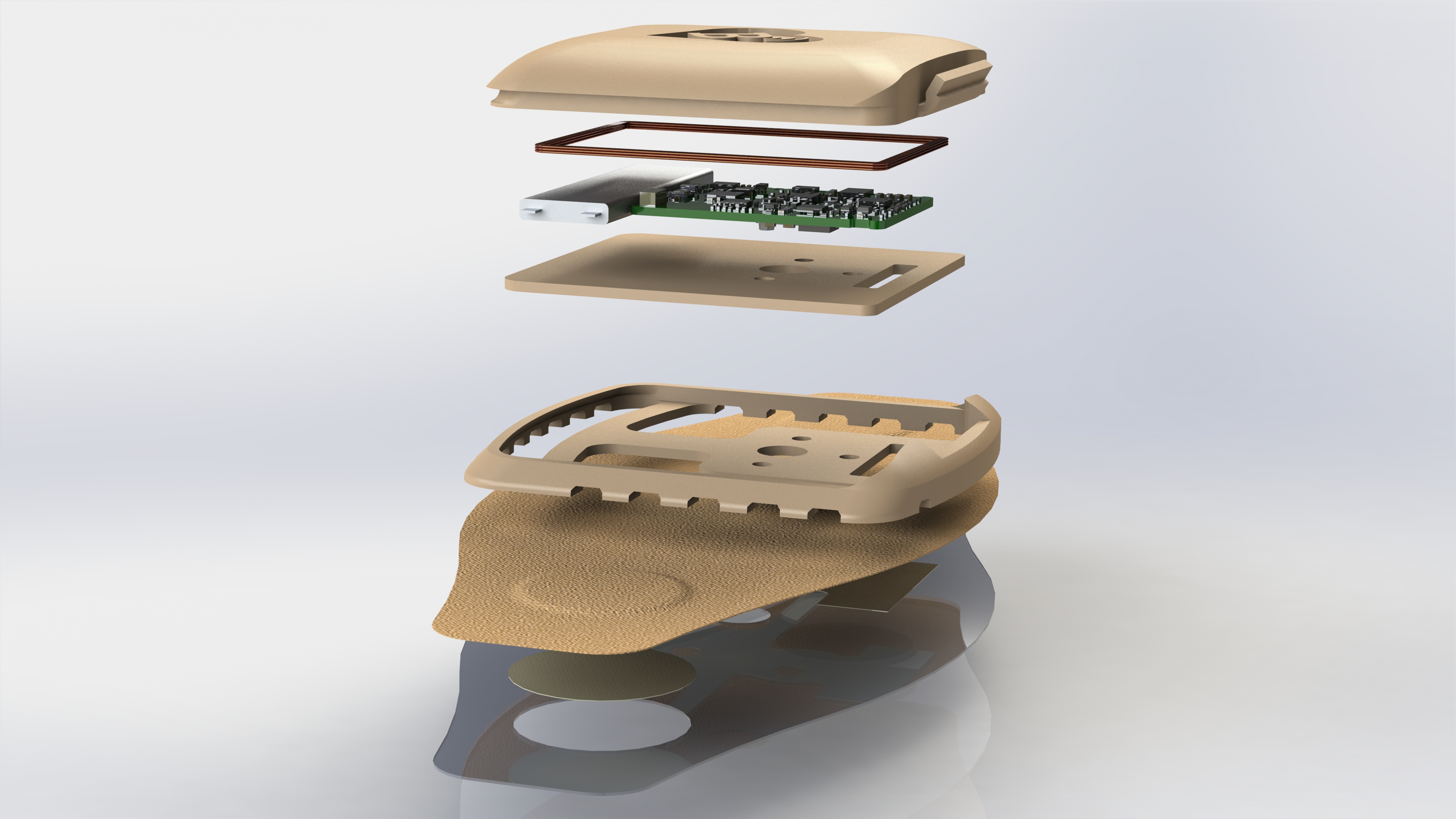
Sensor Patch Top View
Generated three ultra-slim, modular housing design concepts for BraveHeart Wireless
BraveHeart is a biomedical startup working to create a wireless, wearable life sensor system which far exceeds the capabilities of current market solutions
For scale, fabric bandage is under 4.5 in. x 2 in.
Two layouts using a living-hinge clip for secure connection.
Designed around vertical pogo-pin connector in rectangular slot
Clip Configuration with Transparent Fabric
Magnetic Configuration
One layout using phased magnets for easy alignment and attachment
Professionally 3D printed concepts to test feasibility of size and function
Exploded View of Clip Configuration
Electric Skateboard v2
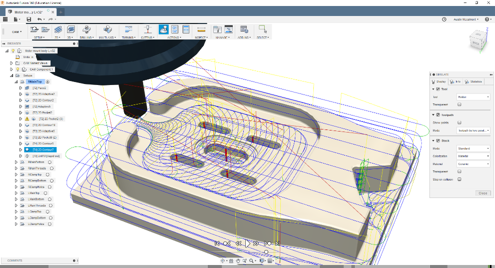
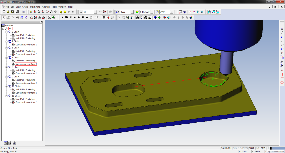
CAM for Motor Mount
Custom CNC’d motor mounts using Fusion 360 CAM
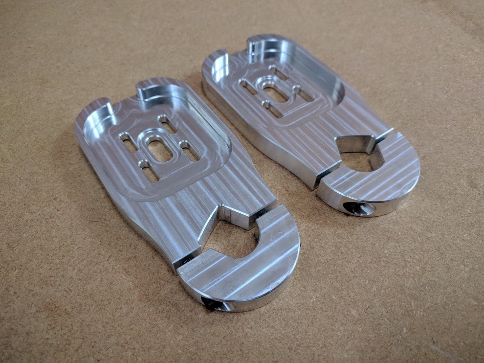
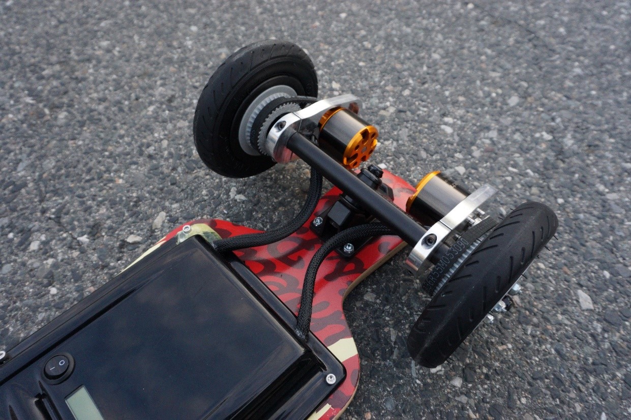
Thicker, clamp-style aluminum motor mounts for easier assembly
CNC'd Motor Mounts
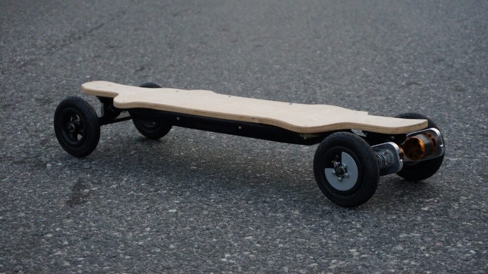
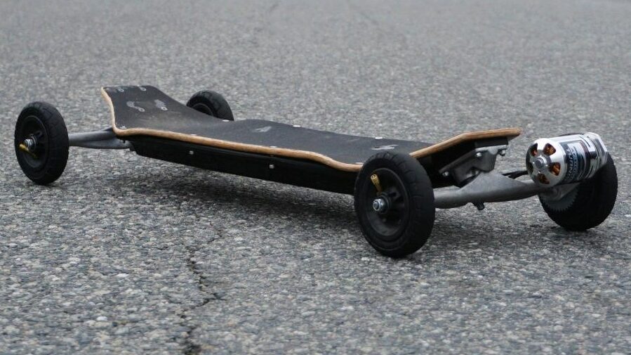
Completed Skateboard
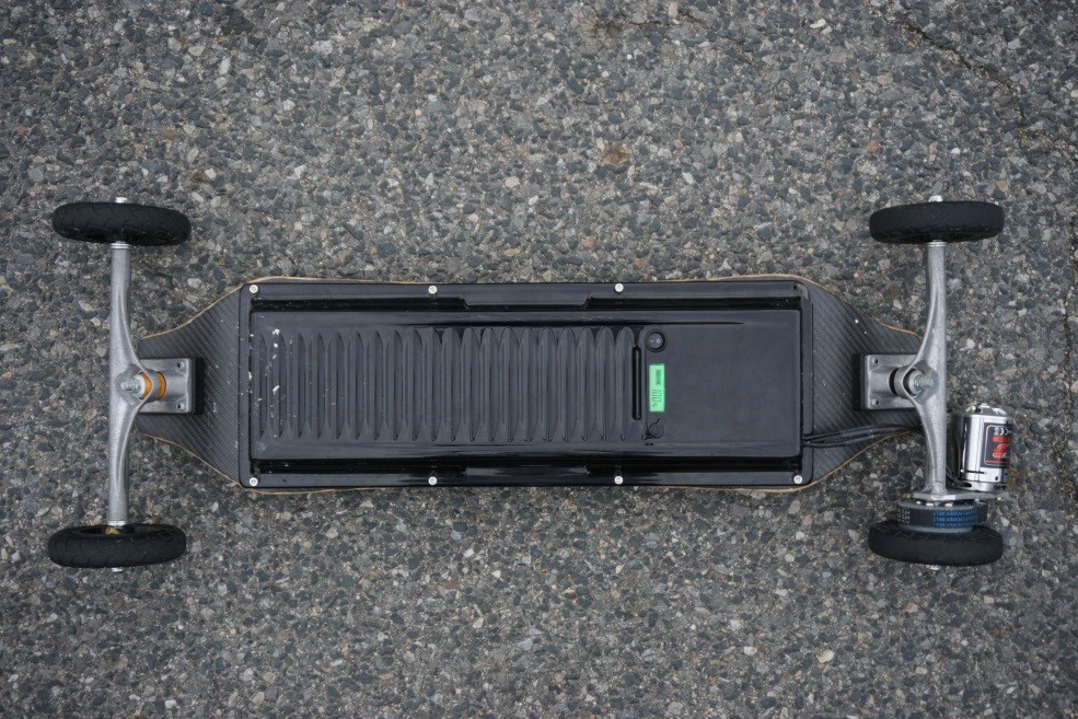
Stiffer, standard-mount longboard deck, higher quality trucks and pneumatic wheels
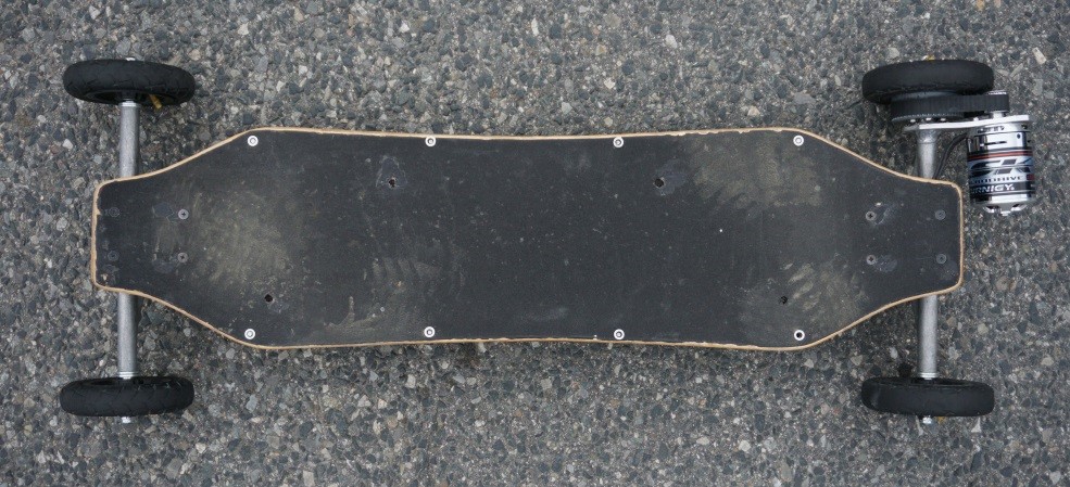
Created an electric skateboard with the goals of being simple, smooth, and quiet
Final product has 23 mph top speed and 10-mile range
Custom CNC’d motor mount
Toolpaths in Esprit CAM
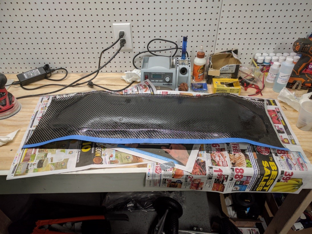
Adding CF to Bottom of Deck
Carbon laminated mountain board deck
Non-standard setup using 125mm pneumatic roller-ski wheels
Top of Skateboard
Bottom of Skateboard
5 Wh Li-ion battery, 3kW motor, belt drive, open source ESC driving with FOC
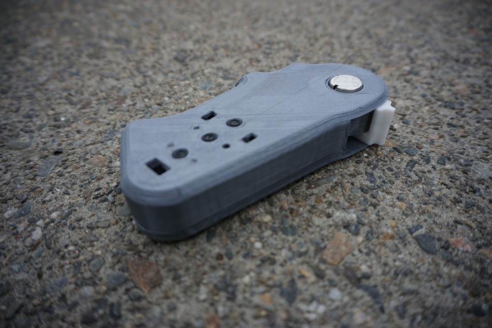
RC car remote fit into compact 3D printed case
Remote in Compact Case
Smart Snow Probe
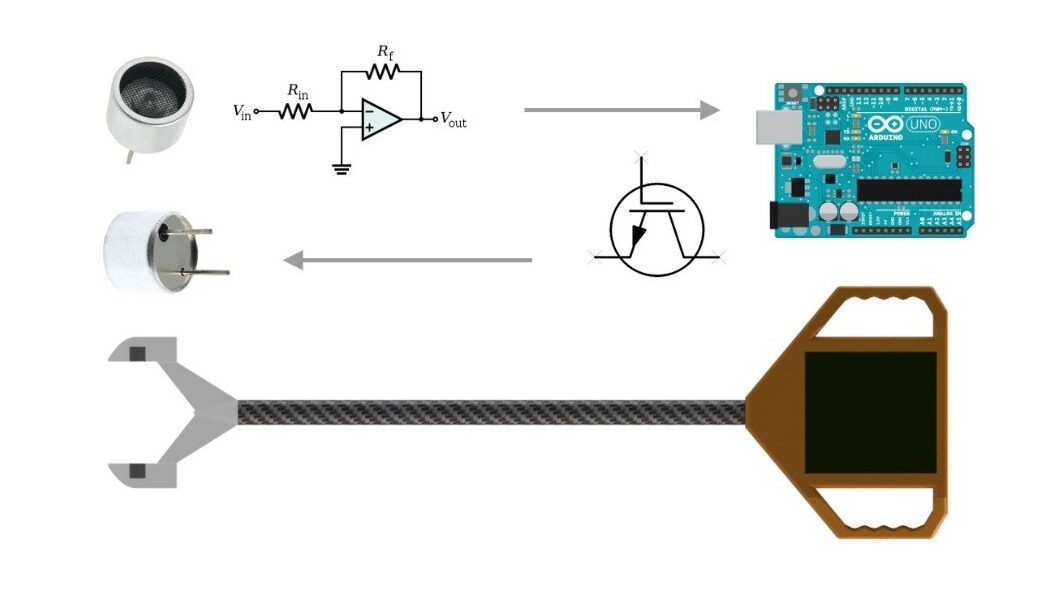
Basic Diagram of Probe Components
Axiomatic design class gave the task of designing anything that could improve snow sports
Conceptualized an electronic snowpack tester that helps winter alpinists better predict and avoid avalanches
Concept uses ultrasonic sensors to plot out snow density vs. depth, which indicates snow instability
Entered idea into WPI competition and won scholarship
Data Supporting Use of Ultrasound
2016
Portable Speaker
Render of Surface Transducing Speaker
Intro to design class gave the task of iterating multiple portable speaker designs in under 7 weeks as a 6-person team using Scrum organization
Led an inexperienced team to a unique final 3D printed solution that utilizes surface transducing technology to create extremely impressive sound quality
Exploded View
Completed Functioning Speaker
Insured final product and presentation were outstanding and completed on time
Inspired a Bose-sponsored WPI senior project team to use this concept in their design
Lathe Automation
Render of Planned Modification
Kineo Inc, in Colorado Springs, Colorado, is an ultra-high precision engineering and machining prototype firm that serves the silicon wafer manufacturing industry
One task at Kineo involved more effectively removing chips during operation on a Fryer lathe
Different solutions were considered in SolidWorks including pneumatic actuated vacuum nozzles and 3D printed vacuum ducting
Fixed and Actuated Vacuum Nozzles
2015
Hexacopter + Gimbal v2
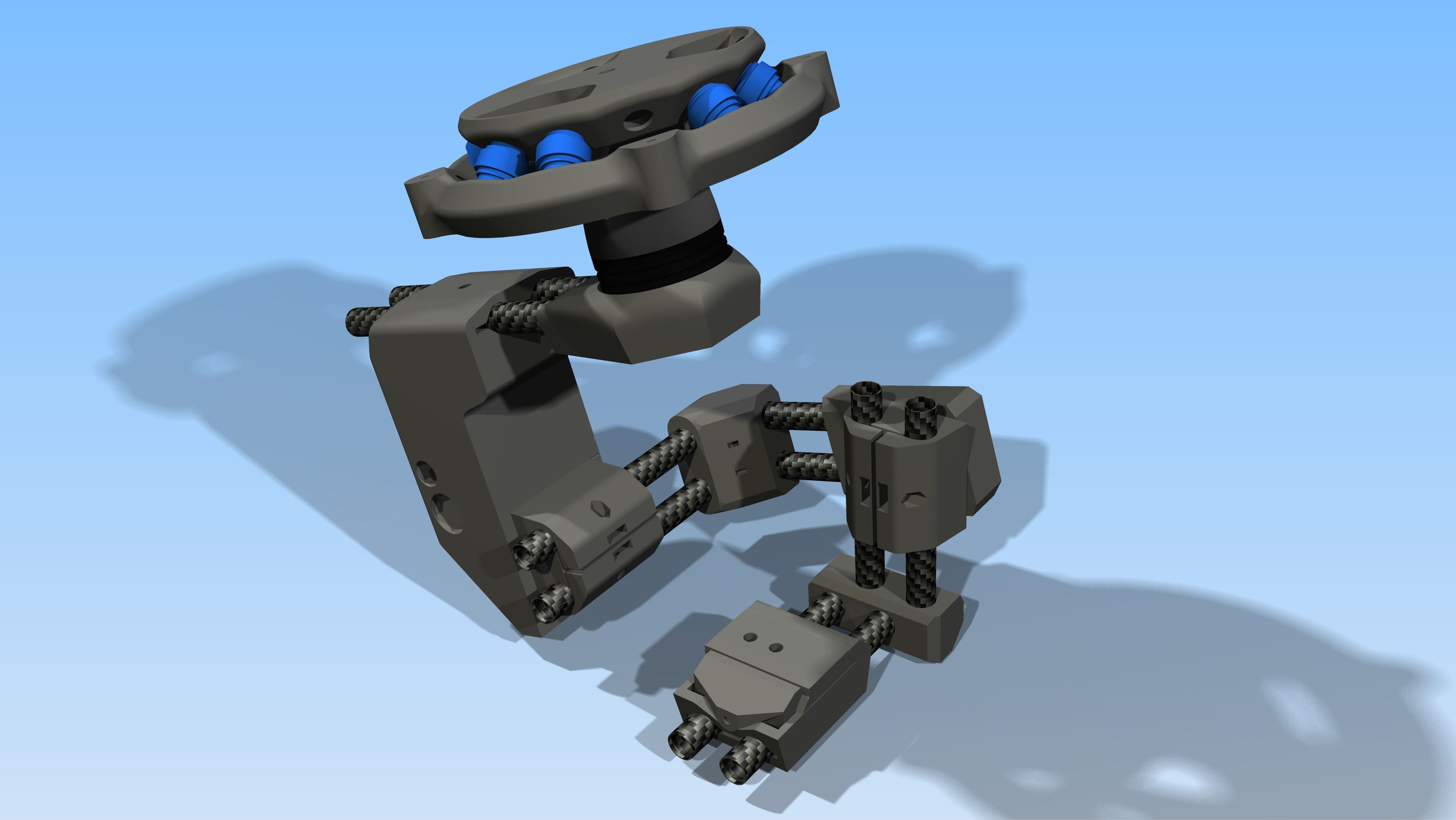
Render of Camera Gimbal v2
Gimbal redesigned with smaller, parallel tubes, central damper, steel fasteners and adjustable camera mount
New enlarged gimbal mount with steel cotter pin and electrical slip ring
Enclosed receiver for dual operator control, bluetooth for changing gimbal settings
External HDMI to AV converter and infrared camera control
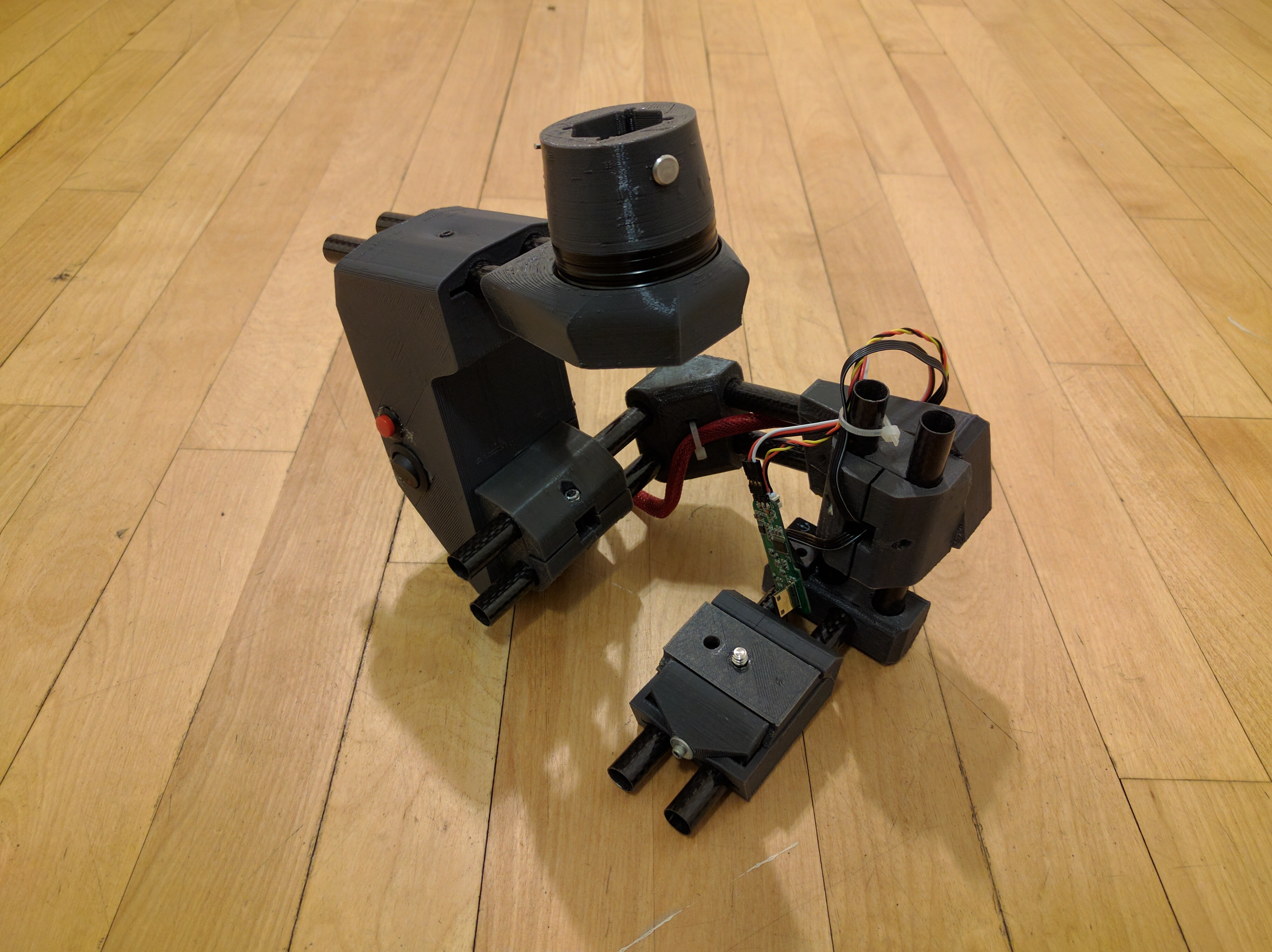
Completed Gimbal
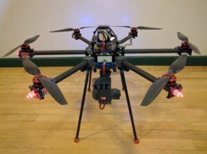
Completed Hexacopter
Hexacopter frame design by Jakub Jewula used to save time
Retractable landing gear to simplify gimbal mount
Custom adjustable brightness lighting
Rear wiring interface for battery with voltmeter and 12 pin gimbal connector
Next steps include redesigning vibration damper and increasing retract reliability
Back of Hexacopter and Gimbal
2014
Y6 v2 + Gimbal v1
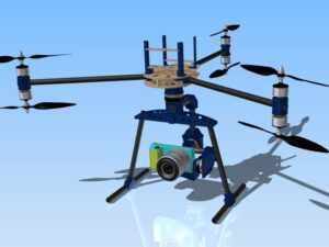
Autodesk Inventor Render of Y6v2 and Brushless Gimbal
Redesigned from version 1 with stronger, higher precision structural components
Brushless gimbal designed around the Sony NEX-5t (swappable to handheld mount in seconds)
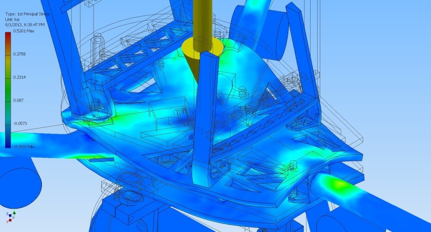
Basic F.E.A. preformed in Autodesk Inventor as an attempt to optimize placement of weight reduction cutouts
Basic FEA to Optimize Lightweighting
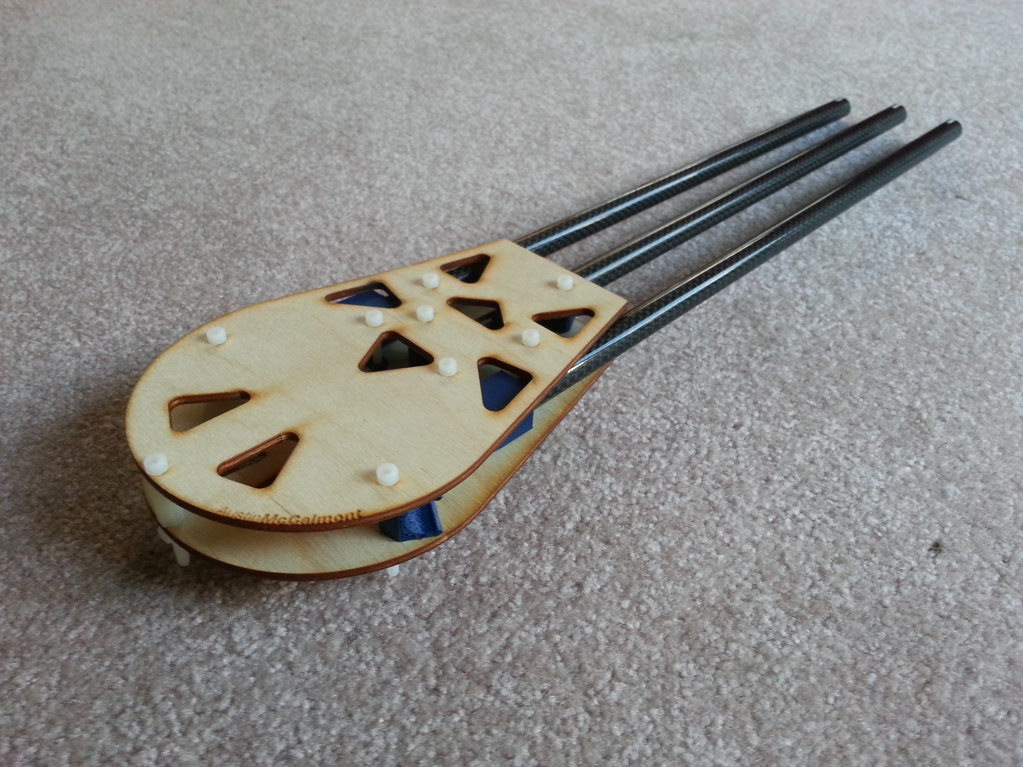
Assembled Folding Frame
Frame laser cut by online manufacturer
3D Printed Boom Clips
Reused wiring harness from version 1
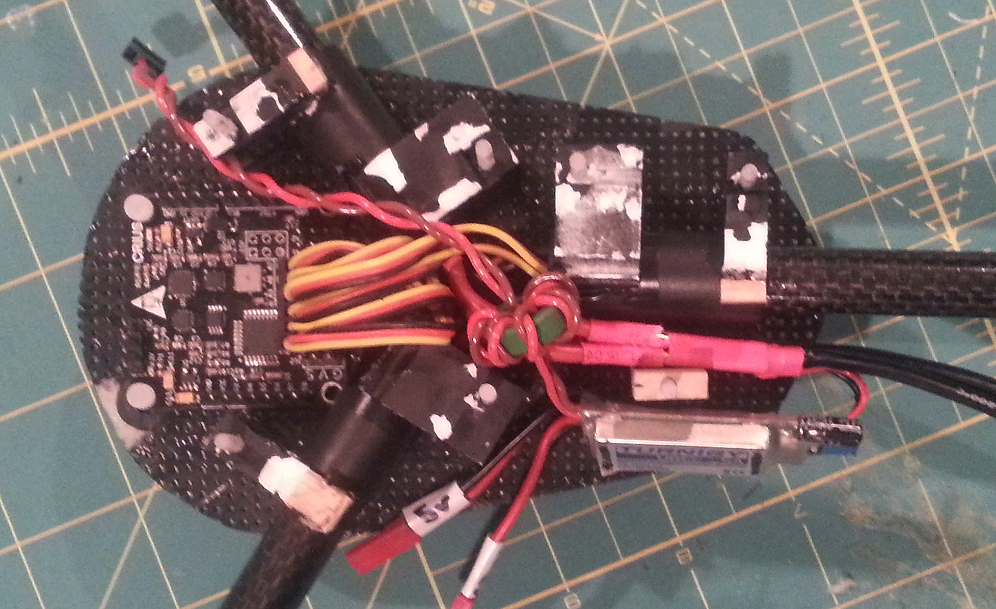
Main Wiring Harness
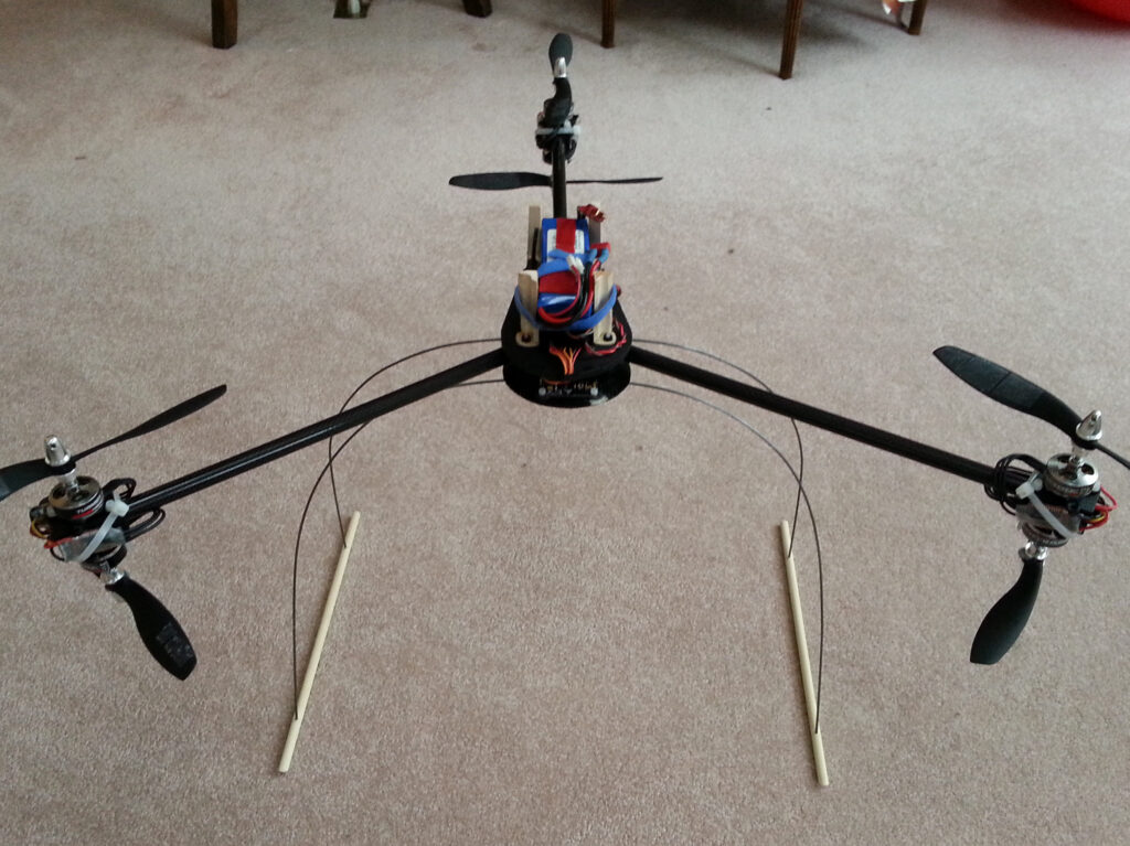
Assembled Y6 with Gimbal
Improved flight characteristics over v1, but still not quite satisfactory performance
Wood plates and nylon bolts still not stiff enough
2013
3D Printer
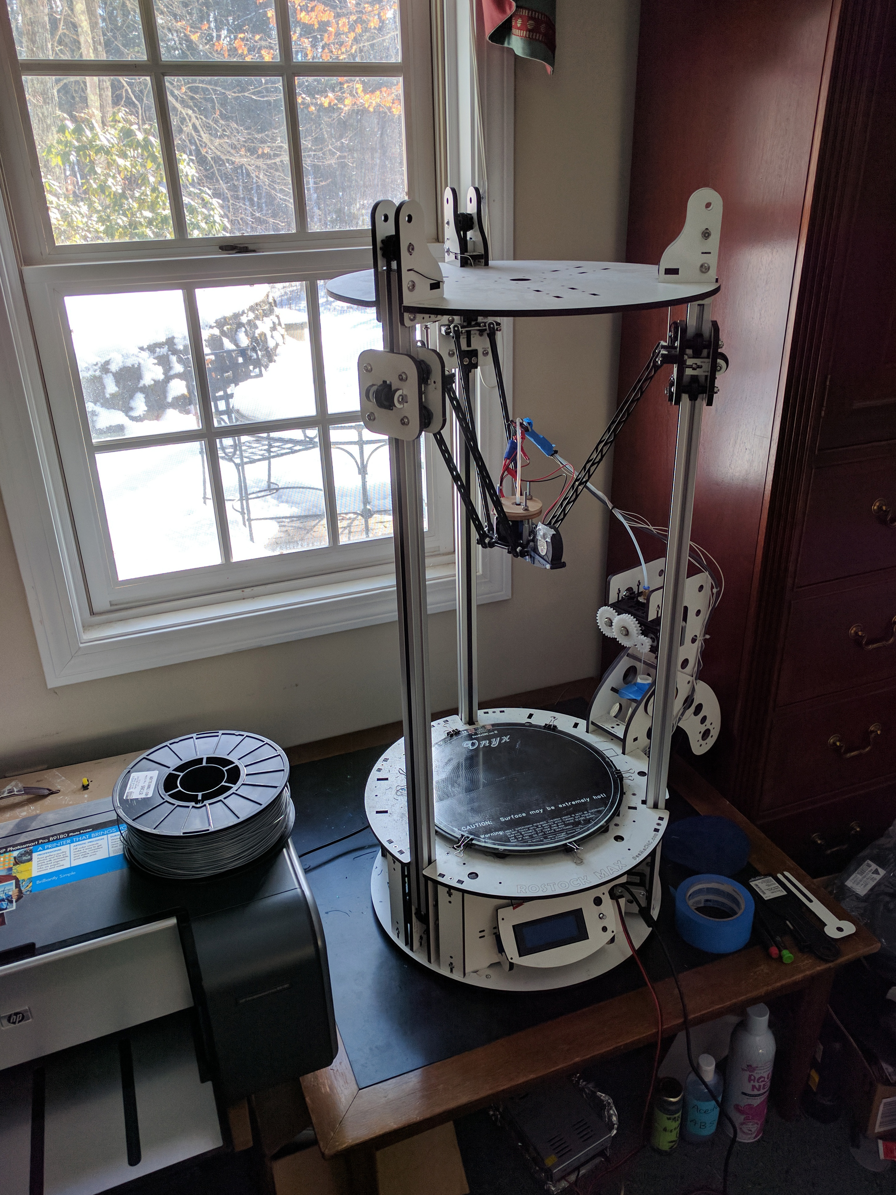
Delta Style 3D Printer
DIY 3D printer from SeeMeCNC built to dramatically increase multirotor design possibilities
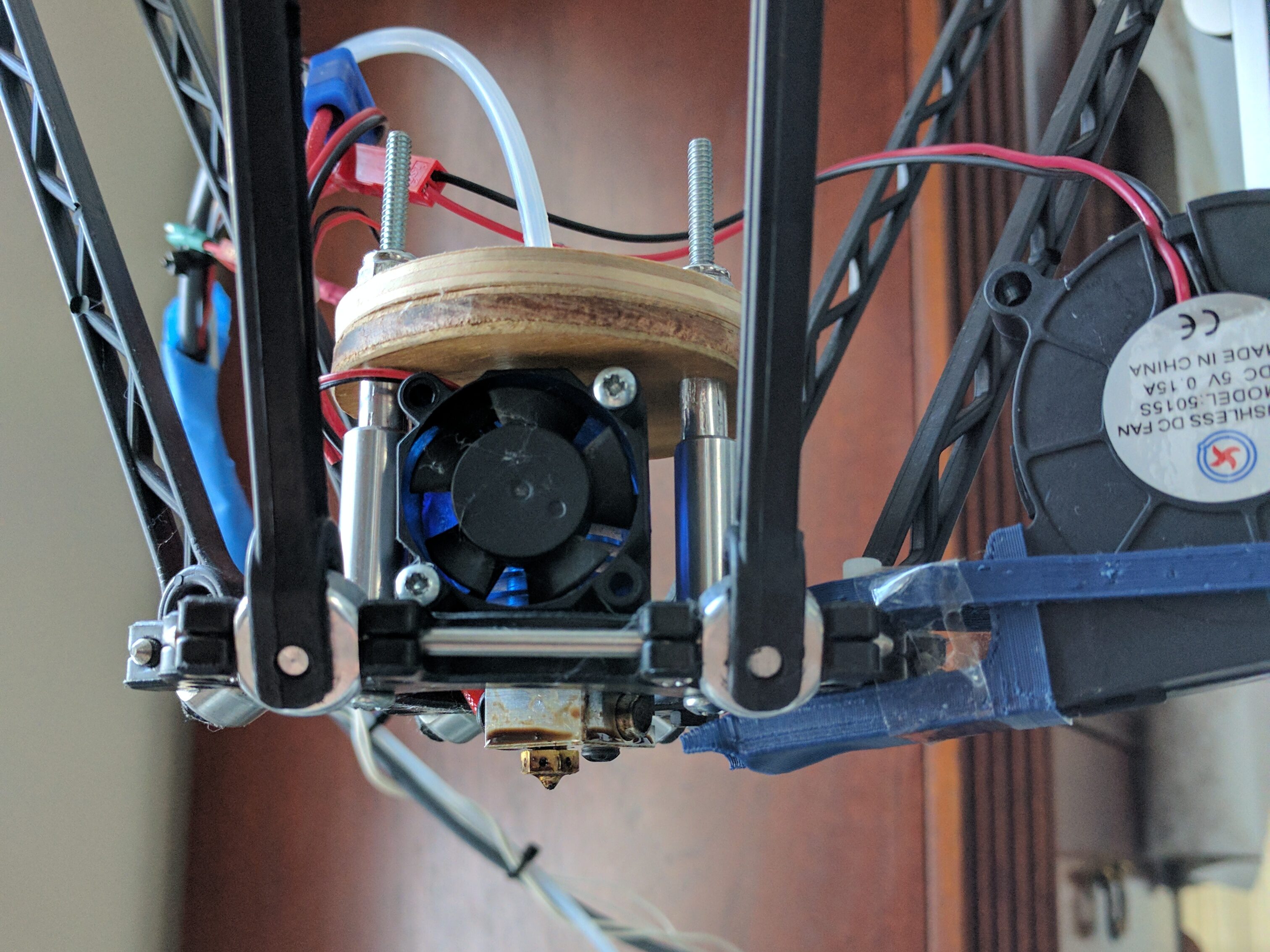
Modified secondary power supply for faster heating and upgraded E3D print head with cooling fan for higher print quality
E3D Hotend with Cooling Fan
2012
Y6 v1
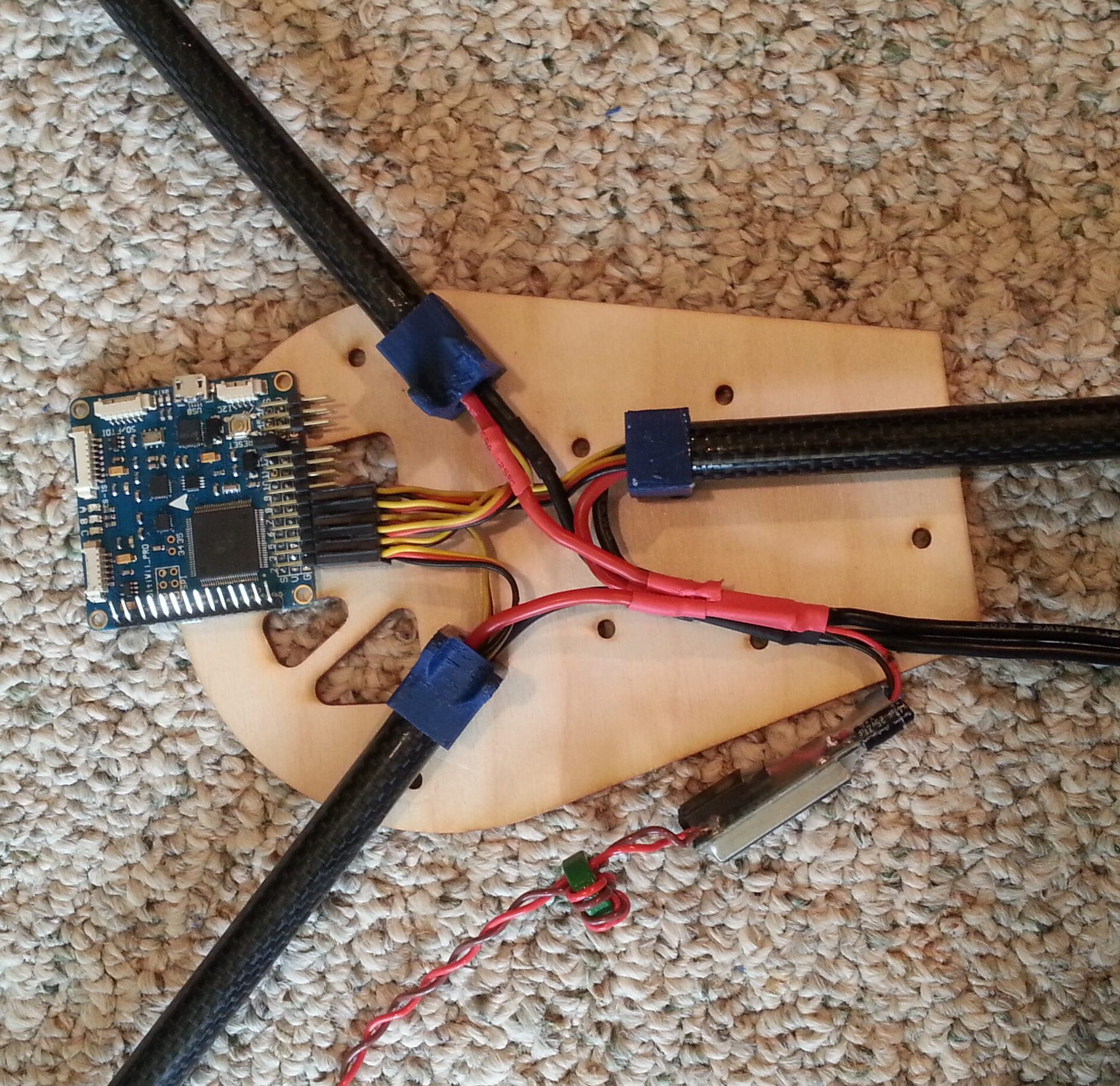
Power System Ready to be Installed
Design goal: Create a portable multirotor capable of carrying a 250 g camcorder on a 2-axis mount
Constraints: High school freshman – Low budget and limited access to manufacturing tools
Design inspired by the Draganflyer X6, one of the few professional multirotors on the market at the time
Folding and crash-absorbing design using pipe clips and sheet metal dampers
All Electronics Installed
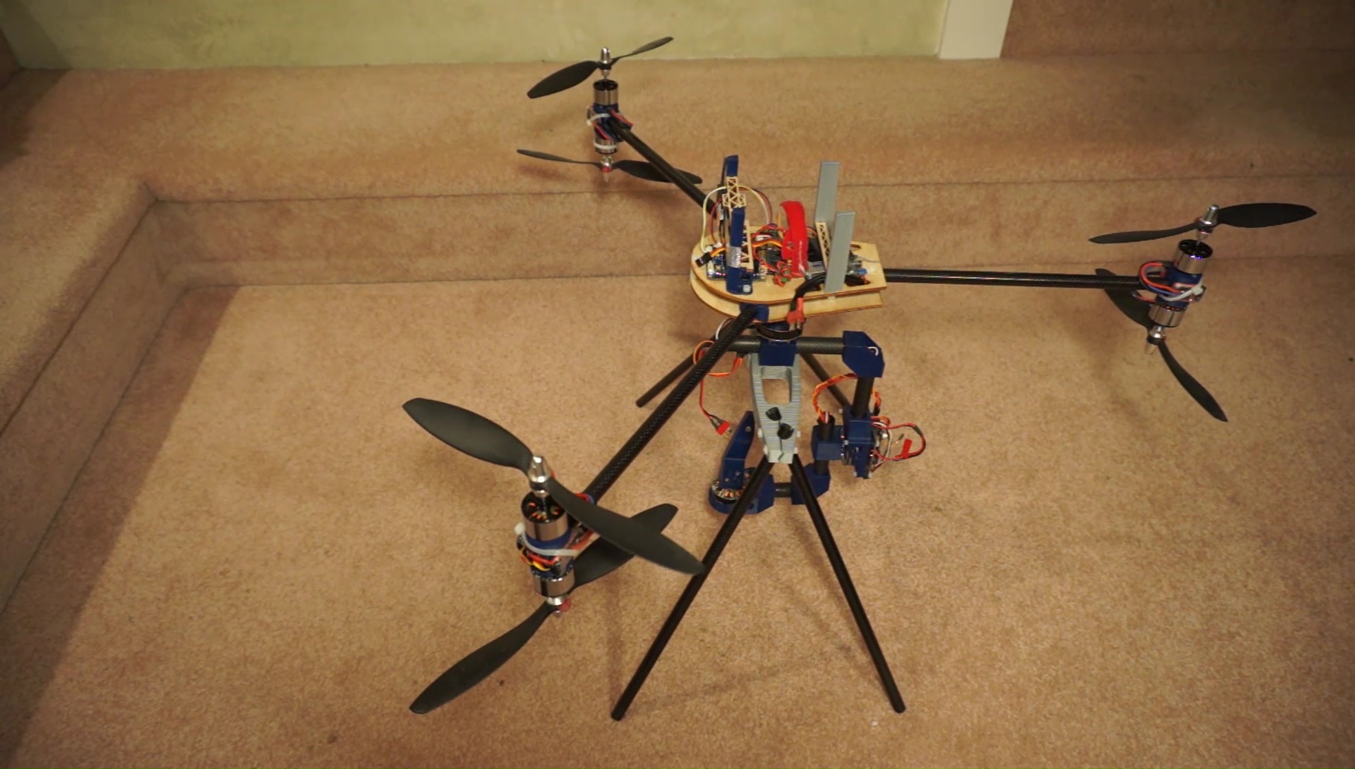
Fully Assembled Y6
Frame was too flexible, resulting in poor flying characteristics
Motors didn’t produce target thrust or flight times despite propeller optimization